CAD to Revit Conversion & BIM Automation Software in India | DesignDrafter
Home breadcrum-svg

Cad to Revit Bim Automation

CAD to Revit Conversion & BIM Automation Software for Indian Architecture & MEP Teams

Our platform streamlines the entire drawing development process by transforming design data into intelligent, standards-compliant technical drawings - instantly.

Try for free

Try for Free!

Discover our features and evaluate their
suitability for your needs.

Sign up
Try for free illustration

Process that covers everything

cardimg
cardimg

Cad to Revit conversion

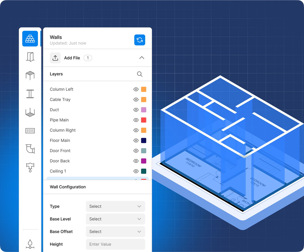
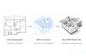
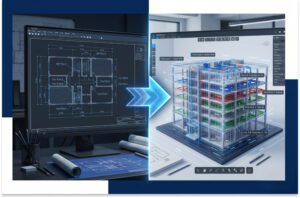
Transform your 2D CAD drawings into intelligent, BIM-ready 3D Revit models with precision and efficiency. Our automated solution streamlines the transition from traditional drafting to advanced Building Information Modeling (BIM), enhancing visualization, coordination, and project execution. User can Convert CAD layouts into detailed Revit BIM models in minutes.

cardimg
cardimg

Project Browser

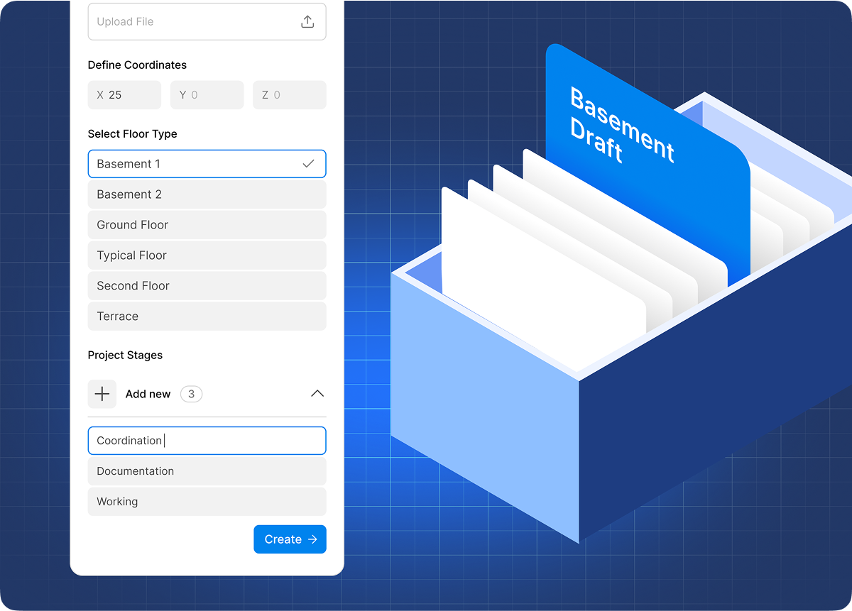
Effortlessly organize and navigate your Revit projects with our intelligent Project Browser Management feature. Our application simplifies the structuring of views, sheets, schedules, and families, ensuring a well-organized Revit workspace for seamless collaboration and efficiency.

Enhance your BIM workflow with an intuitive Project Browser Management system, making Revit navigation faster, smarter, and more efficient.

cardimg
cardimg

Annotation & Dimensioning

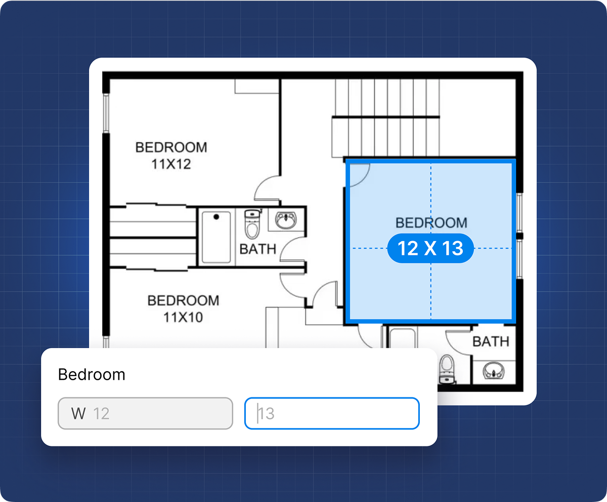
Enhance precision and efficiency with our Auto Annotation & Dimensioning feature, eliminating the need for manual drafting while ensuring compliance with industry standards. Our intelligent system automatically applies annotations, dimensions, and labels to your Revit models, saving time and reducing errors.

Automatically apply aligned, linear, and radial dimensions to building elements with precision. Maintain uniformity in annotations across multiple sheets and views.

cardimg
cardimg

Sections

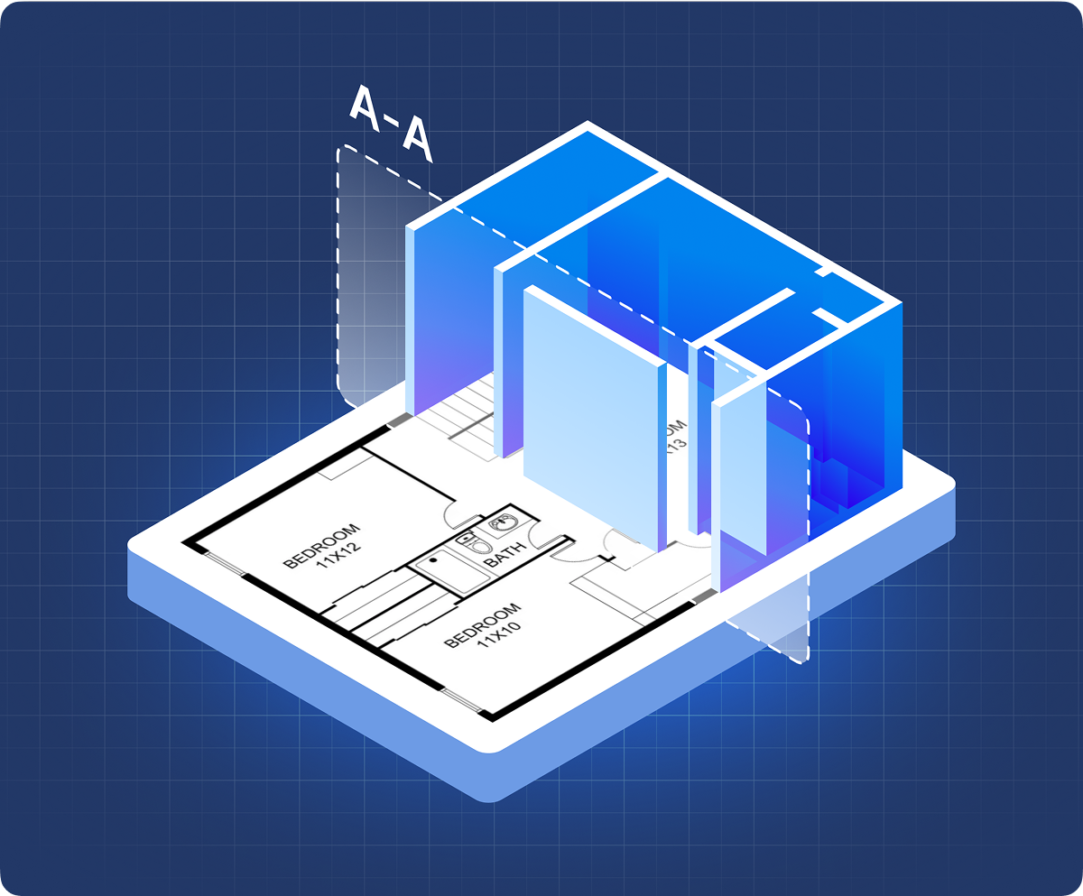
Simplify your workflow with our Automatic Section Creation feature, enabling effortless generation of cross-sections and longitudinal sections in Revit.

No more manual slicing or tedious adjustments—our intelligent system ensures accuracy and efficiency in documenting building elements.

cardimg
cardimg

Legends

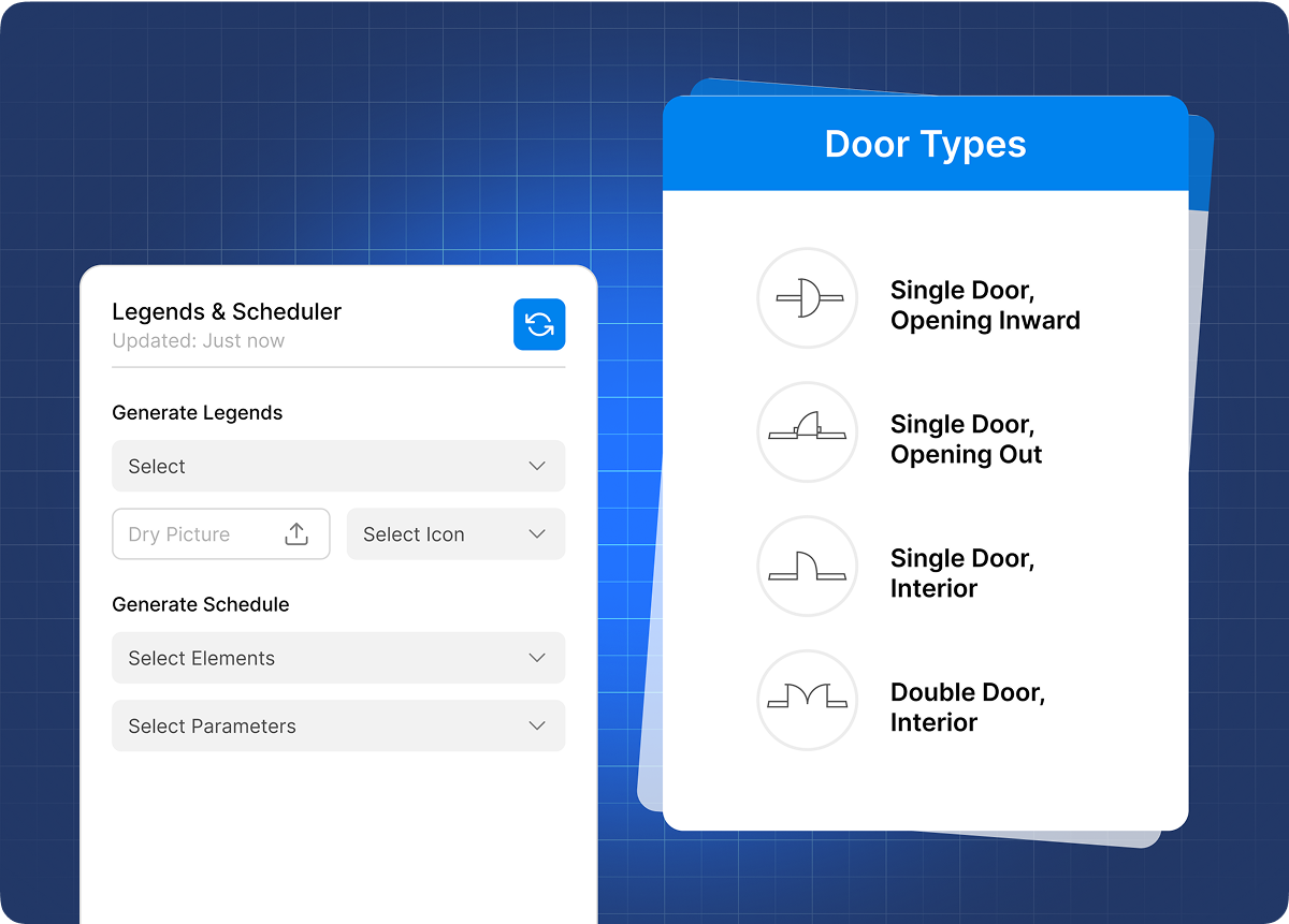
Enhance your Revit documentation with our Automated Legend Generation feature, which creates legends based on provided samples for seamless project standardization.

No more manual drafting—our tool intelligently extracts relevant data and formats legends automatically. Automatically pull material, symbol, and component details from your model. Maintain uniform legend styles across all sheets using predefined templates.

cardimg
cardimg

Sheets

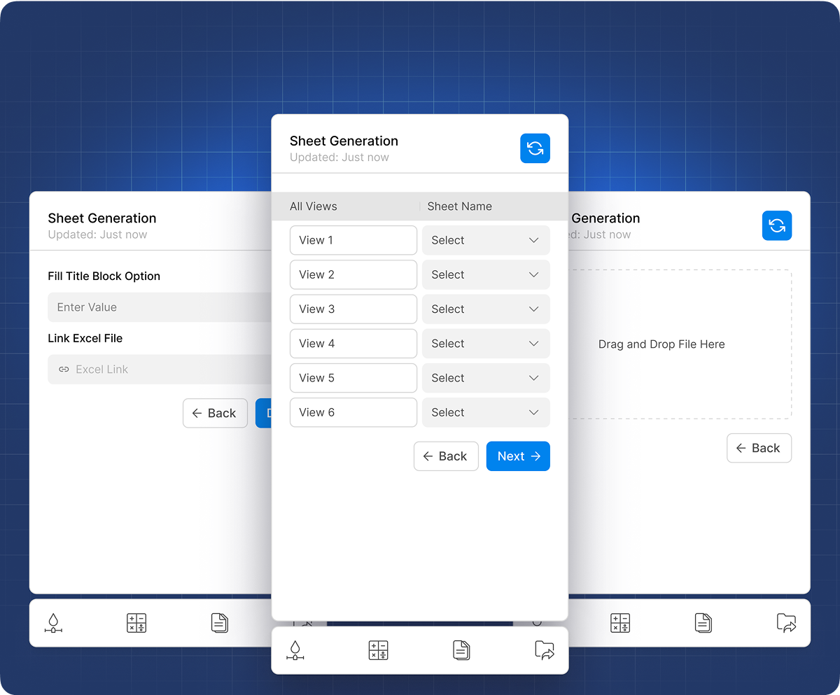
Speed up your project documentation with our Automated Sheet Generation feature, which creates multiple Revit sheets in minutes from a provided drawing list or predefined standards. Eliminate the hassle of manually setting up sheets and focus on design efficiency.

Import drawing lists to automate sheet naming and numbering. Automatically place plans, sections, elevations, and legends in designated locations.

cardimg
cardimg

Clash resolver

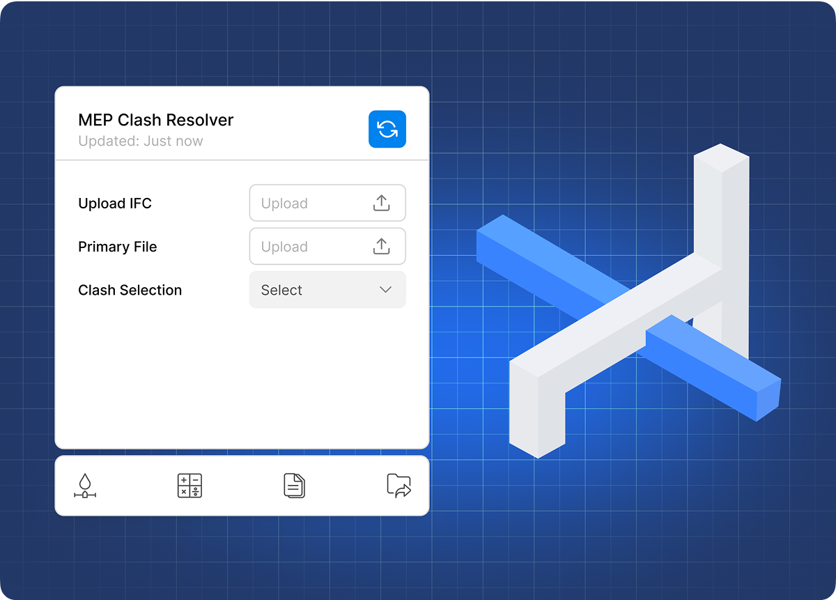
Ensure seamless coordination in your MEP designs with our advanced clash detection and automated route optimization feature. Our application identifies clashes between different building elements and intelligently suggests revised routing solutions, minimizing design conflicts and rework. Get AI-driven suggestions for rerouting MEP components to resolve conflicts.

Seamless Integrations

Streamline your MEP designs with our clash detection and route optimization feature. Our app spots clashes between building elements and suggests smart rerouting solutions to reduce conflicts and rework.

copilot R-logo
teams CAD-logo

FAQ

What is CAD to Revit conversion and why do Indian AEC teams need it?

faq-arrow

CAD to Revit conversion is the process of transforming legacy 2D CAD drawings (DWG or PDF files) into intelligent, object-based 3D Building Information Models (BIM) in Autodesk Revit format. In a 2D CAD drawing, a wall is just a pair of lines. In a Revit BIM model, that same wall is a parametric object with material properties, fire rating, thermal performance, and a direct link to quantity schedules and cost data.

For Indian AEC teams, the need for this conversion is acute because a large proportion of the country’s existing building stock and legacy project documentation exists exclusively as 2D AutoCAD drawings. As clients, contractors, and government bodies increasingly require BIM-level coordination for approvals, tendering, and facility management, firms that cannot efficiently convert their CAD libraries into BIM are locked out of high-value project opportunities.

The traditional approach to this conversion requires a BIM modeler to manually redraft every wall, door, window, duct, pipe, and conduit from the CAD drawing as a BIM object in Revit, a process that takes weeks per project and introduces significant manual error. DesignDrafter’s CAD to Revit BIM Automation replaces this manual workflow with an AI-driven process that reads your 2D drawings, classifies architectural and MEP elements automatically, and builds the intelligent 3D Revit model in a fraction of the time. The output includes full annotation, section creation, legend generation, sheet creation, clash resolution, and Cobie/Uniclass data, making it immediately ready for coordination, documentation, and submission.

What file formats does the CAD to Revit conversion support?

faq-arrow

DesignDrafter’s CAD to Revit conversion accepts 2D CAD drawings in DWG format (AutoCAD native files) and PDF drawings as source inputs, covering the two most common formats in which legacy building drawings exist across Indian AEC firms.

DWG files are the native format of AutoCAD and are produced by virtually all CAD drafting workflows used by Indian architects, structural engineers, and MEP consultants. When a DWG file is uploaded, the AI reads layer structures, line types, blocks, and annotation text to intelligently classify elements such as walls, columns, doors, windows, MEP duct runs, pipe layouts, and electrical conduit paths.

PDF drawings, which are common in project archives, scanned submissions, and client-issued drawing sets, are also accepted. The AI processes the vector or raster content of the PDF to extract geometry, recognize element types, and reconstruct them as BIM-ready objects.

On the output side, the platform produces Revit-compatible models that include structured architectural elements, MEP objects with correct family assignments, fully annotated views, cross-sections and longitudinal sections, automated sheet layouts, and Cobie/Uniclass classification data for facilities management readiness. These outputs integrate directly with existing Revit workflows and coordinate through DesignDrafter’s Clash Resolver before handoff. For teams who want to further use BIM data for procurement and cost planning, the converted models also feed directly into the Quantity Extraction module to generate accurate BOQs automatically.

What does the BIM automation process include beyond just converting CAD lines to Revit objects?

faq-arrow

DesignDrafter’s BIM automation covers seven distinct deliverables that go far beyond simple geometry translation, producing a fully coordinated, documentation-ready BIM model from your source CAD file.

The seven components of the BIM automation workflow are:

CAD to Revit conversion itself, which auto-classifies walls, doors, windows, MEP elements, and structural elements as intelligent Revit objects rather than dumb geometry.

Project Browser Management, which organizes all views, sheets, and model components within Revit’s project browser in a structured hierarchy so the model is immediately navigable by any team member.

Annotation and Dimensioning, which automatically applies aligned, linear, and radial dimensions to building elements and places annotations consistently across all views and sheets, eliminating manual annotation work and maintaining uniformity across a large document set.

Section Creation, which automatically generates cross-sections and longitudinal sections through key building elements, views that typically require significant manual setup time in Revit.

Legend Generation, which creates automated symbol and material legends for all views to ensure documentation completeness and project standardization.

Sheet Creation, which generates multi-discipline drawing sheet sets complete with title blocks, view placement, and revision tracking, turning the model directly into submission-ready documentation.

Clash Resolution, which detects spatial conflicts between architectural, structural, and MEP elements within the model and automatically suggests or applies rerouting solutions to eliminate conflicts before they reach the construction site.

This end-to-end BIM automation workflow eliminates the rework cycle that consumes significant project time when clashes are discovered late in traditional CAD-to-BIM conversion processes. Teams supporting architects, MEP consultants, and contractors benefit from receiving a fully coordinated model rather than a raw geometric conversion.

What is BIM clash detection and how does DesignDrafter's clash resolver work?

faq-arrow

BIM clash detection is the process of identifying spatial conflicts between different building systems within a 3D model, such as an HVAC duct running through a structural beam, a plumbing pipe intersecting an electrical conduit, or a door swing conflicting with equipment placement. These conflicts, called clashes, are invisible in 2D CAD drawings and are one of the leading causes of costly rework on Indian construction sites.

Traditionally, clash detection requires separately modeled discipline models to be federated in Navisworks or BIM 360 Clash, where a coordination team manually reviews hundreds of clash reports and assigns resolution tasks to discipline engineers, who then make changes in their respective Revit models before the process repeats. This cycle can span weeks on complex projects.

DesignDrafter’s Clash Resolver automates both the detection and the resolution steps within the same platform. After the CAD-to-Revit conversion produces an integrated multi-discipline model, the system identifies hard clashes (two elements physically occupying the same space), soft clashes (elements within a defined clearance zone), and workflow clashes (sequencing or access conflicts). For each identified clash, the platform suggests smart rerouting solutions, such as adjusting duct routing to pass below a beam, relocating a pipe sleeve, or modifying equipment clearance zones, and applies these solutions automatically where accepted.

The result is a clash-free or significantly clash-reduced BIM model before any site coordination meeting takes place. For design firms managing multi-discipline coordination on large commercial or infrastructure projects, this transforms clash detection from a reactive, late-stage firefighting exercise into a proactive, automated quality gate built into the BIM production workflow.

How does Cobie and Uniclass data get added to the Revit model during BIM automation?

faq-arrow

Cobie (Construction Operations Building Information Exchange) and Uniclass are structured data standards that classify and organize building component information to support facilities management, maintenance, and asset tracking throughout a building’s operational lifecycle. Adding this data to a BIM model during the design and documentation phase is a mandatory requirement on many government, institutional, and PFI/PPP projects in India and internationally, and a growing requirement across commercial project clients.

In a manual BIM workflow, Cobie and Uniclass data population is a time-consuming administrative task where BIM managers must assign classification codes, system names, component types, and maintenance parameters to every object in the model individually. On a large model, this can take days and is highly prone to inconsistency.

DesignDrafter’s BIM automation populates Cobie and Uniclass data automatically during the conversion process. As the AI classifies each element from the source CAD drawing, it assigns the appropriate Uniclass classification code (covering architectural elements, MEP systems, and structural components) and structures the Cobie data fields required for facility handover, including component type, system, space assignment, and installation data placeholders.

For project teams preparing BIM deliverables for handover to building owners, facility managers, or government asset registries, this automated data population eliminates a major administrative burden and ensures the delivered model meets data completeness requirements on the first submission rather than requiring multiple rounds of data cleanup. It connects directly to the broader AI Design Agent workflow on DesignDrafter, where the agent can execute model quality checks and data validation tasks across the entire BIM deliverable automatically.

How does CAD to Revit BIM automation integrate with MEP design workflows?

faq-arrow

CAD to Revit BIM automation and MEP design are deeply interconnected because an intelligent BIM model is the foundation on which MEP systems are coordinated, sized, and documented. When a 2D CAD drawing is converted to a 3D Revit model, the spatial data it contains, room volumes, ceiling heights, duct shaft locations, pipe riser positions, and equipment room dimensions, becomes the input for accurate MEP design calculations.

On DesignDrafter’s platform, the integration between BIM automation and MEP workflows works in two directions. In the forward direction, an AI-generated or CAD-converted Revit model provides the spatial geometry that drives MEP design calculations: room areas and volumes inform HVAC heat load calculations, floor layouts determine electrical circuit distribution, wet area groupings drive plumbing system sizing, and building height and occupancy data inform fire pump and sprinkler design calculations.

In the reverse direction, completed MEP calculations feed back into the BIM model as system data: duct sizes, pipe diameters, cable routes, sprinkler layouts, and equipment selections become BIM objects in the model, properly classified and coordinated with the architectural structure. The Clash Resolver then checks that all MEP systems fit within the allocated structural and architectural envelope before the model is issued for construction.

For MEP consultants and EPC contractors who currently run CAD drawings and MEP calculations in completely disconnected environments, this integrated workflow eliminates the coordination gap that causes late-stage clashes, design revisions, and site rework.

How much time does BIM automation save compared to manual CAD to Revit conversion?

faq-arrow

Manual CAD to Revit conversion for a medium-complexity building project typically takes 2 to 6 weeks, depending on building size, number of disciplines, and level of detail required. Automated BIM conversion with DesignDrafter compresses this timeline significantly, reducing the conversion and documentation phase to a fraction of the manual effort.

The time savings come from five areas. First, element auto-classification eliminates the manual process of identifying and placing each wall, door, window, and MEP component as a Revit family object. Second, automated annotation and dimensioning removes the drafting time required to label and dimension every view. Third, automatic section and sheet creation replaces hours of view setup and sheet management. Fourth, automated clash detection and routing suggestions eliminate the iterative coordination cycle between discipline engineers. Fifth, Cobie and Uniclass data population removes a significant administrative task at project closeout.

For design firms billing by the hour, this time reduction directly translates to improved project margins on BIM deliverables. For firms working on multiple simultaneous projects, automated BIM conversion allows the same team to handle a significantly higher project load without proportional increases in BIM staffing. The freed-up capacity is redirected toward higher-value design and engineering tasks, such as using the AI Floor Plan Studio to explore layout options or running MEP calculations to validate the design before issue.

Is BIM automation suitable for both residential and commercial projects in India?

faq-arrow

Yes, DesignDrafter’s CAD to Revit BIM automation is designed for the full range of Indian building project types, from residential apartments and housing societies to large commercial towers, hospitals, educational campuses, and industrial facilities.

The BIM automation workflow adapts to project type through the variety of Revit family categories, Uniclass classifications, and MEP system types it recognizes. For residential projects, the conversion handles architectural elements (walls, slabs, staircases, balconies), plumbing fixtures, electrical DB layouts, and fire sprinkler coverage. For commercial projects, the automation extends to more complex MEP systems: central chiller plants, primary and secondary HVAC distribution, multi-tier electrical distribution boards, standpipe fire systems, and high-rise plumbing with booster pump zones.

For institutional and industrial projects, where BIM deliverables are increasingly mandated by clients and regulatory bodies, the platform’s ability to deliver Cobie/Uniclass-populated models with full annotation and clash resolution means project teams can meet BIM Level 2 and higher delivery requirements without substantially increasing their delivery costs.

DesignDrafter’s pricing plans scale to project size and team capacity. Individual consultants and small firms working on residential and low-rise commercial projects can access CAD to Revit conversion as part of the Starter Plan, while larger teams working on multi-discipline high-rise or institutional projects benefit from the Professional and Team plans, which include multi-discipline coordination tools and priority support.

How is DesignDrafter's CAD to Revit automation different from using Revit's built-in import tools?

faq-arrow

Revit’s built-in CAD import function brings DWG geometry into Revit as a linked or exploded drawing reference, not as intelligent BIM objects. Every element remains a dumb line or polyline until an engineer manually traces over it and assigns the correct Revit family and parameter data. This is why manual CAD to BIM conversion takes weeks; Revit’s import tool is a reference overlay, not a conversion engine.

DesignDrafter’s CAD to Revit automation uses AI to go beyond geometry import. The AI reads the layer naming conventions, block references, line weights, and annotation text in the DWG file to infer the building element type for each entity. A wall layer becomes a Revit wall family with the correct type and material. A fixture block becomes a Revit MEP fixture with the correct category, system, and parameter assignments. A duct centerline with dimensions becomes a Revit duct with correct size and system routing.

The distinction matters enormously in practice. A Revit model produced by DesignDrafter’s automation is a living, schedulable, coordinatable BIM model where walls appear in door/window schedules, pipes appear in plumbing take-off schedules, and MEP equipment appears in equipment lists. A model produced by Revit’s built-in import is simply a background reference that requires complete manual remodeling before it can support any of these BIM workflows. Combined with automated sheet creation and clash resolution, DesignDrafter delivers what would take a skilled BIM team weeks to produce manually.

Can the BIM model output from DesignDrafter be used for quantity takeoffs and BOQ generation?

faq-arrow

Yes, one of the most valuable downstream uses of a DesignDrafter-produced BIM model is automated quantity extraction and BOQ generation. Because the model contains intelligent, classified BIM objects with correct geometry and parameter data, quantities can be extracted directly from the model rather than being manually measured from 2D drawings.

The integration between BIM automation and Quantity Extraction is a core part of the DesignDrafter platform workflow. After the CAD-to-Revit conversion produces a classified, coordinated BIM model, that model can be uploaded directly into the Quantity Extraction module, which analyzes the BIM data and extracts accurate material quantities, dimensions, and specifications for all architectural and MEP elements. The outputs are formatted as BOQ-ready documents that can be exported in PDF or Excel for procurement, tendering, and client proposals.

For Indian AEC firms where manual quantity take-off from 2D drawings is still the norm, this end-to-end workflow from CAD drawing to BIM model to BOQ within a single platform represents a fundamental shift in how pre-construction cost information is produced. What currently requires a dedicated estimating team working from drawings for days can be compressed into a significantly shorter cycle with far higher accuracy, because quantities are derived directly from the building geometry rather than from manual measurement with its inherent approximation errors.