Homebreadcrum-svg

MEP Design Calculations

Automated MEP Design Calculation Software for Engineers - Electrical, HVAC, Fire & Plumbing

Heat load, cable sizing, sprinkler hydraulics and pipe sizing, worked out in one workspace and checked against IS, NBC, ECBC, ASHRAE and NFPA. Every report shows its inputs and working, ready for you to check and sign off.

Start free
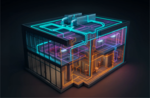
The design calculation workspace: light fixtures and cabling are placed, the supply duct runs to a diffuser in every room, sprinkler heads and pipework are laid out, and supply and drainage lines reach every fixture, each checked against its code.
Free plan

Try for Free!

Discover our features and evaluate their suitability for your needs.

Start freeNo credit card required

MEP design calculation, from project inputs
to a report you sign off

Electrical, HVAC, plumbing and fire calculations share one project file, so every discipline works from the same floor areas and occupancy. Design Calculation does the repetitive working; your engineers make the design decisions and sign off the results.

  1. STEP 01
    Set up the project file

    Enter the location, building type, occupancy and the design standards that apply. Import an existing CAD or BIM model, or start from scratch.

  2. STEP 02
    Run the calculations

    Add occupancy loads, ventilation rates, electrical demand and fixture counts. Design Calculation works out heating and cooling loads, lighting levels and water demand, each checked against the relevant ASHRAE, NFPA, IPC or IS code.

  3. STEP 03
    Export the reports

    Export calculation reports in PDF or Excel, showing the inputs, the clause applied and each step. Layout drawings export in CAD or Revit format.

Electrical Design Calculations in DesignDrafter
01 · Electrical

Electrical Design Calculations

  • IS / IEC
  • DIALux
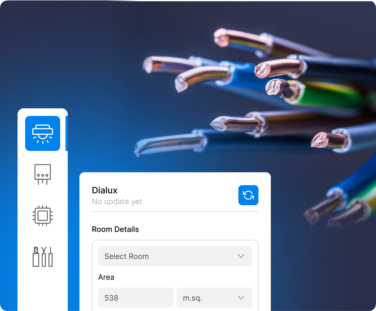
DIALux - Lighting Design Calculation
Work out lux levels for indoor and outdoor spaces from fixture type, spacing, mounting height and room geometry, checked against IS:3646 and the ECBC energy density targets.
Breaker Size Calculation
Size each breaker from the load analysis, allowing for short-circuit capacity (kA rating), overload protection and coordination with upstream and downstream devices, checked against IS/IEC.
Distribution Board (DB) Details
Allocate lighting, power and HVAC circuits across DB panels, with busbar ratings and phase balancing per floor and zone. The output is a DB schedule and a single-line diagram (SLD).
Cable Sizing Calculation
Get the conductor size for each circuit from voltage drop, current-carrying capacity (ambient temperature, grouping) and short-circuit withstand, checked against IS/IEC.
HVAC Design Calculations in DesignDrafter
02 · HVAC

HVAC Design Calculations

  • ASHRAE 62.1
  • ISHRAE
Heat Load Calculation
Enter the location, orientation, glazing, occupancy and equipment loads, and get the sensible and latent heat load for each zone, following ASHRAE and ISHRAE methods.
Ventilation Calculation
Work out fresh air per person and per space type, and air changes per hour (ACH), checked against ASHRAE 62.1, ISHRAE and local building codes.
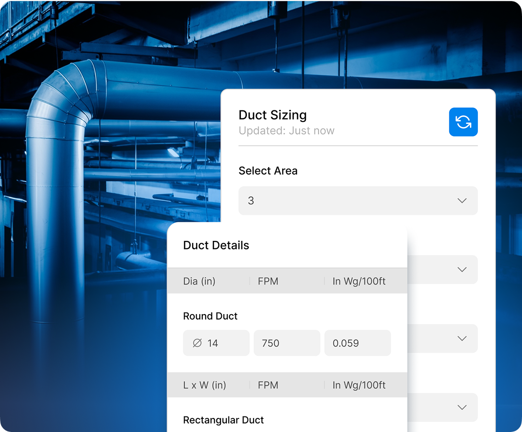
Duct Sizing Calculation
Size each duct run from airflow demand and static pressure loss, by the equal friction, velocity reduction or static regain method.
Equipment Selection & Energy Efficiency
Select chillers, AHUs, FCUs or VRF/VRV systems from the calculated loads, with COP and EER checked against the ECBC efficiency targets.
Fire Fighting Design Calculations in DesignDrafter
03 · Fire Fighting

Fire Fighting Design Calculations

  • NFPA 13
  • NFPA 20
  • NBC
  • FM Global
Head Loss Calculation
Calculate friction losses in the fire piping by Hazen-Williams or Darcy-Weisbach, from pipe material, diameter, flow rate and fittings, and check the residual pressure at the most hydraulically remote sprinkler or hydrant.
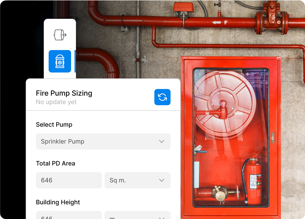
Fire Pump Sizing Calculation
Get the pump capacity (GPM/LPM) and pressure (PSI/kPa) from the sprinkler and hydrant demand, then choose electric, diesel and jockey pumps, checked against NFPA 20 and NBC.
Sprinkler System Design Calculation
Set the hazard class for each zone (light, ordinary or extra) and get head spacing, discharge density and minimum operating pressure, checked against NFPA 13, NBC or FM Global.
Hydrant & Hose Reel System Design
Work out the flow at each hydrant, standpipe sizes for multi-storey buildings and the pressure to run the hose streams NBC requires for the building’s occupancy and height.
Plumbing Design Calculations in DesignDrafter
04 · Plumbing

Plumbing Design Calculations

  • UPC
  • IPC
  • IS codes
Water Supply System Sizing
Get peak water demand from occupancy and fixture count, then pipe sizes from flow rate, velocity limits and pressure loss, checked against UPC, IPC and IS codes.
Pressure & Head Loss Calculation
Calculate the pressure drop from pipe length, fittings and changes in level, and check the pressure left at each fixture against the plumbing code minimum.
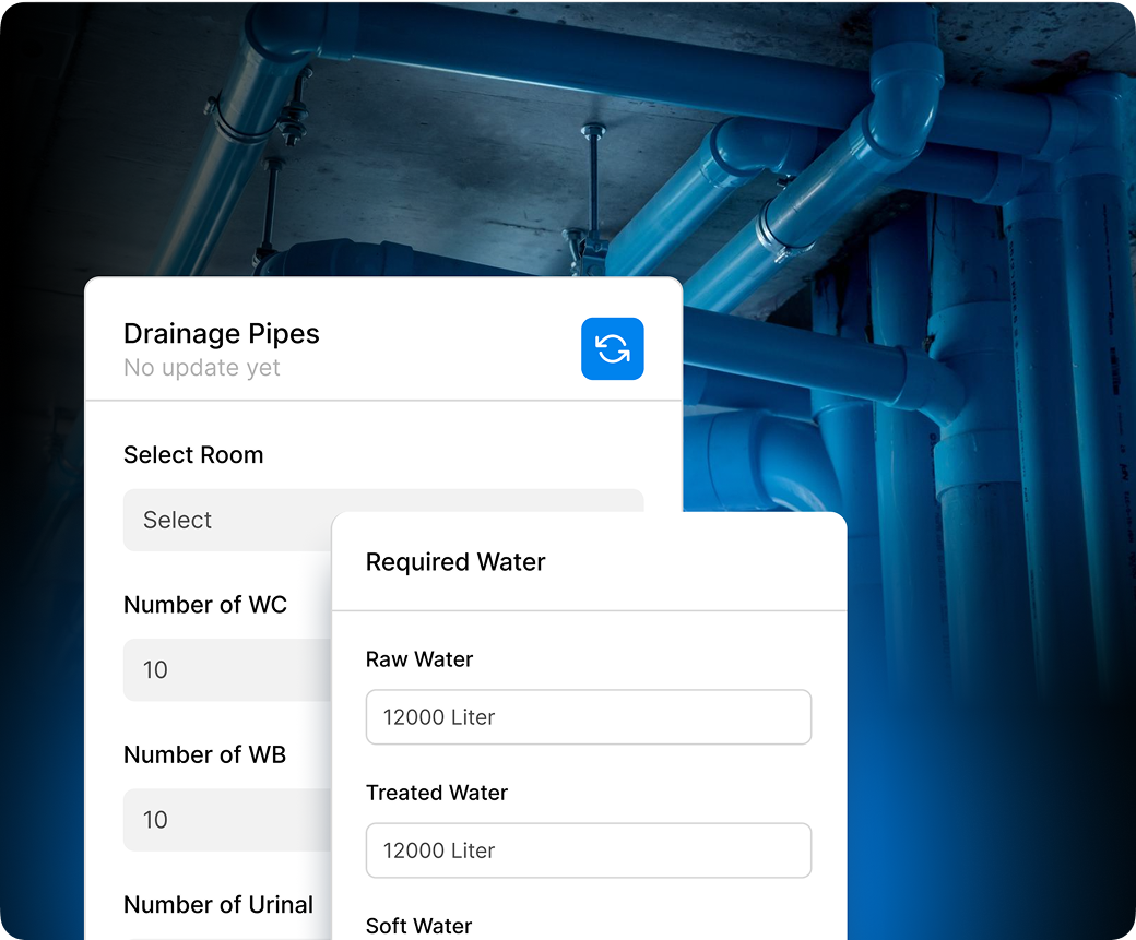
Drainage & Sewer System Design
Size drainage pipes from drainage fixture units (DFU), set slope and venting, and size sewage pumps and sump pits for below-grade discharge.
Rainwater & Stormwater Drainage Calculation
Size rainwater pipes from roof area and rainfall intensity, and plan stormwater retention, discharge and rainwater harvesting.
Code-referenced outputs

Calculations that cite the standards you submit against

Every calculation report lists the clause it applied, so the same document works for client review, municipal approval and internal QA.

  • NBC
  • IS / IEC
  • ECBC
  • ISHRAE
  • ASHRAE
  • NFPA
  • IS:15105
  • IS:1172
  • UPC-I

Works with the tools you already use

DesignDrafter works alongside Revit and AutoCAD rather than replacing them. Bring in your CAD drawings, convert them to Revit models, and send layouts, calculations and quantities back into your existing BIM workflow.

copilotR-logo
teamsCAD-logo

Blogs

Related Blogs

March 27, 2026

Complete Guide to AI-Powered MEP Design Calculations: Electrical, HVAC, Plumbing & Fire

This guide shows how platforms like DesignDrafter’s Design Calculation are helping engineers move from concept to validated design in a fraction of the traditional timeline.

Learn more arrow

April 14, 2026

Electrical Load Calculation for Buildings: The Complete Step-by-Step Guide for Engineers and Architects

This guide walks you through the entire process of electrical load calculation for buildings. You will learn what it is, why it matters, the standards involved, the step-by-step methodology, common mistakes to avoid.

Learn more arrow

May 7, 2026

MEP Drawing Software vs MEP Design Software: What Every Engineer Actually Needs in 2026

This guide shows you what to look for when choosing the right tool, and walks you through how the MEP software landscape has shifted in 2026 with AI now sitting at the center of almost every serious workflow.

Learn more arrow

FAQ

What is MEP design calculation software, and why do engineers in India need it?

faq-arrow

MEP design calculation software is a digital engineering tool that automates the mathematical calculations required to design Mechanical, Electrical, and Plumbing systems in a building. In the context of building engineering, MEP covers four core disciplines: electrical systems (load analysis, cable sizing, lighting design), HVAC systems (heat load, duct sizing, ventilation), plumbing systems (water supply, drainage, pipe sizing), and fire fighting systems (sprinkler design, hydrant coverage, pump sizing).

For engineers in India specifically, the need for dedicated MEP calculation software is driven by three factors. First, Indian projects must comply with a layered set of codes: the National Building Code (NBC), IS/IEC electrical standards, ECBC and ISHRAE for energy and HVAC, IS:1172 and UPC-I for plumbing, and NBC + NFPA + IS:15105 for fire safety. Managing these standards manually across disconnected spreadsheets introduces errors that can delay project approvals and create safety risks. Second, Indian AEC projects are growing rapidly in scale and complexity, from large residential townships to commercial towers and industrial facilities, demanding faster turnaround on engineering calculations. Third, traditional MEP calculation workflows in India rely on multiple disconnected tools (Carrier HAP for HVAC, DIALux for lighting, separate spreadsheets for plumbing), which creates coordination gaps and rework.

DesignDrafter’s Design Calculation solves all three problems by automating all four MEP disciplines in a single workspace, with every calculation checked against Indian codes from the start. You can read a detailed breakdown of how this compares to traditional approaches on the DesignDrafter blog covering MEP drawing software versus MEP design software.

What types of MEP calculations does DesignDrafter's software perform?

faq-arrow

DesignDrafter performs a comprehensive set of MEP engineering calculations across all four building services disciplines: Electrical, HVAC, Fire Fighting, and Plumbing. Here is a complete breakdown of what each discipline covers on the DesignDrafter Design Calculation platform:

For Electrical calculations, the platform handles DIALux-based lighting design and illuminance level optimization, circuit breaker sizing based on load analysis and short-circuit conditions, Distribution Board (DB) layout with busbar ratings and circuit allocation, and cable sizing based on voltage drop, current-carrying capacity, and thermal constraints.

For HVAC calculations, it performs heat load calculations based on building size, occupancy, orientation, and climate data; ventilation calculations per ASHRAE 62.1, ISHRAE, and local codes; duct sizing using equal friction, velocity reduction, and static regain methods; and equipment selection for chillers, AHUs, FCUs, and VRF/VRV systems with COP optimization.

For Fire Fighting calculations, the platform covers head loss analysis using Hazen-Williams and Darcy-Weisbach equations, fire pump sizing (GPM/LPM and PSI/kPa) per NFPA 20, sprinkler system design per NFPA 13 and NBC, and hydrant and hose reel system design for multi-storey buildings.

For Plumbing calculations, it addresses water supply system sizing based on occupancy and fixture count, pressure and head loss analysis across the pipe network, drainage and sewer system design using Drainage Fixture Units (DFU), and rainwater and stormwater drainage calculations based on roof area and rainfall intensity.

This breadth of calculation coverage in one platform is what separates DesignDrafter from tools like Carrier HAP (HVAC only), DIALux (lighting only), or h2x (plumbing only). Teams supporting architects, MEP consultants, and EPC contractors can handle an entire building’s engineering calculations without switching tools.

Which Indian and international building codes does the MEP calculation software comply with?

faq-arrow

DesignDrafter’s Design Calculation checks its calculations against the main Indian and international standards for building services engineering. The code checks are not a manual checklist; they are built into the calculation logic of each discipline.

For Electrical design, calculations follow IS/IEC standards, covering load analysis, cable sizing, breaker ratings, DB design, and lighting levels as required by the Bureau of Indian Standards and the International Electrotechnical Commission.

For HVAC design, the platform applies ASHRAE 62.1 for ventilation rates, ECBC (Energy Conservation Building Code) for energy performance compliance, and ISHRAE (Indian Society of Heating, Refrigerating and Air Conditioning Engineers) guidelines for India-specific climate and occupancy conditions.

For Plumbing design, calculations are checked against IS:1172 (code of basic requirements for water supply and sanitation), UPC-I (Uniform Plumbing Code India), and NBC plumbing norms covering drainage fixture loading, pipe sizing, and pressure requirements.

For Fire Fighting design, outputs are checked against NBC (National Building Code of India), NFPA 13 and NFPA 20 (National Fire Protection Association standards for sprinklers and fire pumps), and IS:15105 (Indian Standard for fire suppression systems).

Covering all of these standards matters because Indian building projects often require submission of engineering calculations to multiple authorities, including local municipal bodies, fire departments, and energy compliance offices. Code-referenced outputs that your engineer has checked can shorten approval cycles. You can explore how these calculations connect to full-building design on the DesignDrafter AI Design Agent page, where the AI runs these workflows for your engineers to review and sign off.

How does automated MEP calculation software reduce errors compared to manual calculations?

faq-arrow

Automated MEP calculation software reduces engineering errors by tackling the three root causes of mistakes in manual workflows: manual data entry, formula inconsistencies across disconnected spreadsheets, and missing interdisciplinary cross-checks. Manual calculation errors are a common cause of site rework, coordination failures, and project delays.

Here is how automation changes the error profile on DesignDrafter’s platform:

First, input-driven automation means that when you define building parameters such as occupancy type, area, location, and building type once in the project file, those values propagate consistently across electrical, HVAC, plumbing, and fire calculations. This reduces the risk of a floor area being entered differently in the HVAC spreadsheet and the electrical DB schedule.

Second, the calculation engine applies verified formulas aligned with IS/IEC, ASHRAE, ECBC, NBC, and NFPA standards. Engineers do not need to manually reference code tables, interpolate values, or update formula references when project parameters change.

Third, because all four MEP disciplines operate in the same workspace and share project data, interdisciplinary conflicts are surfaced early. For example, if a duct sizing calculation increases the ceiling void requirement, that information is available to the electrical and structural teams in the same session rather than discovered during site coordination.

Fourth, the platform automatically generates detailed calculation reports for export, which are formatted for submission to approval authorities after your engineer has reviewed them. This eliminates the reformatting step that often introduces transcription errors when moving from calculation workbooks to submission documents.

For teams who also work on BIM models and CAD-to-Revit workflows, the structured calculation outputs from DesignDrafter feed directly into BIM coordination without manual re-entry of system data.

How does the HVAC heat load calculation work in the software, and which method does it use?

faq-arrow

DesignDrafter’s HVAC heat load calculation uses building-specific inputs to determine cooling and heating loads, applying industry-standard methodologies aligned with ASHRAE and ISHRAE guidelines. The calculation considers the full set of variables required for a reliable HVAC design: building geometry and floor area, external climate data based on building location, orientation and glazing ratios, occupancy density and internal heat gains from people, lighting, and equipment, and envelope thermal performance (U-values and shading).

The workflow on the HVAC calculation module follows these steps. First, you define the building type and location, which sets the relevant outdoor design conditions (dry-bulb and wet-bulb temperatures for summer and winter). Second, you input room-by-room occupancy, lighting load, and equipment load data. Third, the platform calculates the total sensible and latent heat loads for each zone. Fourth, based on the aggregated loads, it sizes primary equipment: chillers for central systems, AHUs for central air handling, FCUs for zone-level control, or VRF/VRV systems for multi-split configurations. Equipment selection is optimized for COP (Coefficient of Performance) to align with ECBC energy efficiency targets.

Beyond load calculation, the platform handles ventilation rate calculations per ASHRAE 62.1 (minimum fresh air per person per space type) and duct sizing using equal friction, velocity reduction, or static regain methods, depending on the system configuration. This end-to-end HVAC calculation workflow, from initial load to equipment selection to duct sizing, is what tools like Carrier HAP or IESVE handle in isolation. DesignDrafter delivers the same rigor but connects HVAC outputs directly to the building’s electrical load calculations, plumbing system sizing, and overall BOQ through the Quantity Extraction module.

Can the software handle electrical load calculations and Distribution Board (DB) design for Indian buildings?

faq-arrow

Yes, DesignDrafter’s electrical calculation module handles the complete chain of electrical design for Indian buildings, from initial load estimation through to Distribution Board layout and cable sizing, all aligned with IS/IEC standards.

The electrical design workflow on the DesignDrafter platform covers four interconnected calculation areas:

Lighting design calculations use the lumen method to calculate illuminance levels (lux) for indoor and outdoor spaces based on fixture type, spacing, mounting height, and room geometry. The outputs are checked against IS:3646 and the energy density targets under ECBC.

Electrical load calculations determine the connected load and maximum demand for each circuit, floor, and the building overall. Inputs include occupancy type, floor area, load density factors, and power factor. The platform applies the demand factor methodology from IS standards to determine the realistic maximum demand that drives transformer and feeder sizing.

Breaker sizing calculations use the load analysis outputs to select correct circuit breaker ratings, accounting for short-circuit capacity (kA rating), overload protection requirements, and selective coordination between upstream and downstream protection devices.

Distribution Board design allocates circuits across DB panels with correct busbar ratings, phase balancing across three-phase supply, and load distribution per floor and per zone. The DB schedule output is formatted for tender documents and approval submissions, ready for your review.

Cable sizing calculations determine conductor cross-sections for each circuit based on voltage drop limits (typically 3 percent for final circuits per IS standards), current-carrying capacity under installation conditions (ambient temperature, grouping factors), and short-circuit thermal withstand requirements.

This level of integrated electrical calculation directly supports the work of MEP consultants and design firms who currently rely on a combination of Excel spreadsheets, DIALux, and manual DB schedules to produce the same outputs.

How does the fire fighting design calculation module work, and which fire safety standards does it follow?

faq-arrow

DesignDrafter’s fire fighting design calculation module automates the hydraulic and system design calculations required for complete fire protection systems in Indian buildings, following NBC, NFPA, and IS:15105 standards.

Fire protection engineering involves two layers of calculation: hydraulic calculations to ensure adequate water flow and pressure throughout the system, and system design calculations to correctly size and position suppression and detection equipment. Both layers are handled within the fire fighting calculation module.

Head loss calculations determine the frictional pressure losses in the fire protection piping network using the Hazen-Williams equation (the standard method for fire systems) or the Darcy-Weisbach equation for more complex pipe configurations. Inputs include pipe material, diameter, flow rate, pipe length, and fitting losses. The calculation identifies bottleneck sections in the network and optimizes pipe routing to maintain adequate residual pressure at the most hydraulically remote sprinkler or hydrant.

Fire pump sizing calculations determine the required pump capacity in GPM or LPM and system pressure in PSI or kPa based on the hydraulic demand of the sprinkler and hydrant networks. The platform selects the appropriate pump type (electric main pump, diesel backup pump, or jockey pump for pressure maintenance) as required by NFPA 20 and NBC fire system provisions.

Sprinkler system design calculates sprinkler head spacing, discharge density (mm/min over area), and minimum operating pressure per NFPA 13, NBC, and FM Global standards. The system is optimized for the hazard classification of each occupancy zone, whether light hazard (offices), ordinary hazard (commercial), or extra hazard (industrial or storage).

Hydrant and hose reel system design computes the flow demand at each hydrant point, the standpipe sizing for multi-storey buildings, and the pressure requirements to support simultaneous operation of the number of hose streams required by NBC for the building’s occupancy and height.

These calculations integrate directly with the building’s floor plan layout generated by DesignDrafter’s Generate Layout, ensuring that fire system design is spatially coordinated with the architectural layout from the earliest design stage.

Can MEP design calculation outputs be exported for client submissions and regulatory approvals in India?

faq-arrow

Yes, DesignDrafter automatically generates detailed, formatted calculation reports that are structured for client submissions, government authority approvals, and project documentation in India. This is one of the most practically important features for consulting engineers who spend significant time reformatting calculation workbooks into presentable submission documents.

The export workflow works as follows. After completing calculations across any or all of the four MEP disciplines (Electrical, HVAC, Fire, Plumbing), the platform generates structured calculation reports that include all input parameters, methodology references (citing the specific IS, NBC, ASHRAE, or NFPA clause applied), intermediate calculation steps, and final output values. These reports are available in PDF and Excel formats.

The structured format of these reports serves three distinct purposes. For client presentations, the reports show the working and the clauses applied, in a format that is readable by project managers and owners without requiring engineering background. For municipal and regulatory submissions, the reports cite the applicable Indian and international standards by clause, which is the format building permit offices, fire departments, and energy compliance authorities typically expect. For internal QA and coordination, the calculation outputs serve as the basis for MEP equipment specifications, which feed directly into the DesignDrafter Quantity Extraction module to generate BOQs and material specifications.

For teams working across multiple projects simultaneously, Studio Complete brings every calculation discipline into the same project workspace with 15 active projects, so engineers from different disciplines produce coordinated submissions rather than assembling separate reports from disconnected tools.

How does DesignDrafter's MEP calculation software integrate with BIM tools like Revit and AutoCAD?

faq-arrow

DesignDrafter’s MEP calculation outputs are structured for direct integration into BIM workflows, and the platform connects with Revit and AutoCAD through its CAD-to-BIM automation capabilities, eliminating the need to manually re-enter calculated system data into BIM models.

In a traditional MEP workflow, an engineer runs calculations in separate tools (Carrier HAP, DIALux, Excel), then a BIM modeler manually interprets those results and builds the Revit model accordingly. This manual transfer step is both time-consuming and a significant source of error, because the modeler must interpret calculation notes and translate them into BIM object parameters without a direct data link.

DesignDrafter closes this gap through two integration pathways. The first pathway is direct output alignment: calculation reports from the platform are structured with the same system parameters (duct dimensions, pipe sizes, electrical circuit data, equipment capacities) that BIM modelers need to configure MEP objects in Revit. This makes the handoff from calculation to BIM modeling significantly faster and more accurate.

The second pathway is through DesignDrafter’s CAD to Revit service, which uses AI to read 2D drawings (including those annotated with MEP system data from calculation outputs) and transform them into structured, object-based 3D Revit models. The conversion includes full annotation, sheet creation, circuiting and DB details, clash resolution, and COBie/Uniclass data population.

Additionally, the platform integrates with Microsoft Teams and AutoCAD through its integrations, meaning design teams using standard AEC collaboration workflows can incorporate DesignDrafter calculation outputs without changing their existing project delivery infrastructure. For teams interested in how AI also assists with design coordination across disciplines, the AI Design Agent retains full project context and can run MEP calculation tasks, check outputs, and prepare documentation for your engineers to review.

What is the pricing for DesignDrafter's MEP Design Calculation software, and is there a free plan?

faq-arrow

DesignDrafter has a Free plan with no credit card required, credit-based AI plans for individual consultants and small firms, and Studio plans for MEP firms that need full control, with Design Calculation available as a standalone module or as part of an all-modules bundle.

Here is the complete pricing structure on DesignDrafter (prices for India; other regions are billed in USD or EUR):

The Free plan costs nothing, needs no credit card, and gives you 100 credits a month, 1 project and limited access to all modules including Design Calculation. This is designed to let engineers run actual calculations and evaluate the platform before committing to a paid plan.

DesignDrafter AI Plus (₹2,999 per month) gives one engineer 3,000 credits a month across all modules, 3 projects, and PDF, CAD and IFC exports. Team (₹9,999 per month) shares 10,000 credits and 10 projects between up to 5 people, with priority processing. Top-up credit packs are available any time.

Studio Single (₹54,999 per seat per month) is for consultants who want full control over one module. Choose Design Calculation to get every discipline, 5 active projects, unlimited archived projects and 20,000 AI credits per seat.

Studio Complete (₹99,999 per seat per month) bundles Design Calculation, Generate Layout and Quantity Extraction with every calculation discipline (Architecture, Structure, HVAC, Electrical, Plumbing, Fire Fighting), File Flow, 15 active projects, priority processing and 50,000 AI credits per seat. Enterprise is priced on request and adds project management, every project region, org admin and SSO, and API access with an SLA.

Compared to the alternative of licensing separate tools (Carrier HAP for HVAC, DIALux for electrical, h2x for plumbing, and separate fire calculation software), DesignDrafter’s all-in-one pricing delivers substantially better value while also eliminating the coordination overhead of managing four disconnected tools. MEP consultants and design firms working across multiple building types benefit most from Studio Complete, which allows multi-discipline project coordination within a single workspace. Annual billing gives you 2 months free, and you can start for free instantly using your Google account at DesignDrafter.