Designing a safe and efficient electrical system begins long before a single wire is pulled through conduit. It starts with an accurate electrical load calculation. Whether you are working on a residential project, a multi-story commercial complex, or a mixed-use development, understanding how to calculate electrical load properly is the foundation of every successful electrical design.
This guide walks you through the entire process of electrical load calculation for buildings. You will learn what it is, why it matters, the standards involved, the step-by-step methodology, common mistakes to avoid, and how modern AI-powered tools are making this traditionally time-consuming process faster and more reliable.
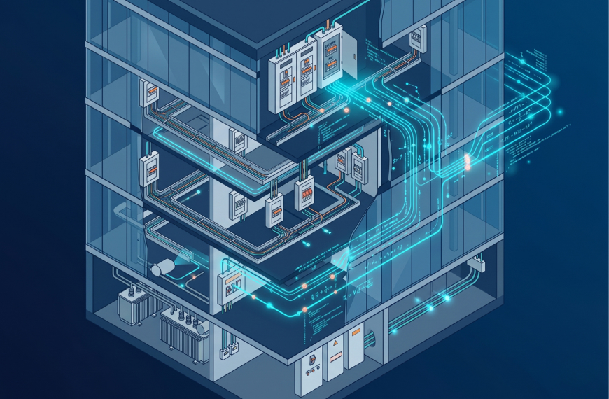
An electrical load calculation is the process of estimating the total amount of electrical power that a building or facility will require under normal operating conditions. Engineers and designers use this calculation to determine the appropriate sizes for conductors, circuit breakers, transformers, panels, and the main service entrance equipment.
At its core, the calculation answers a simple question: how much electricity does this building need? The answer, however, involves careful analysis of every connected load, from lighting fixtures and power outlets to HVAC equipment, elevators, fire pumps, and specialized machinery.
Without a proper load calculation, buildings face serious risks. Undersized systems can overheat, trip breakers frequently, and create fire hazards. Oversized systems waste money on unnecessary equipment and increase capital costs for developers and building owners.
Getting the electrical load calculation right has implications far beyond the electrical room. It affects the overall building design, energy performance, safety compliance, and project budget. Here is why every architect, engineer, and contractor should treat it as a critical step.
Safety and code compliance are the most obvious reasons. Electrical codes such as the National Electrical Code (NEC) in the United States and IS/IEC standards in India require engineers to perform load calculations before designing any electrical system. Building inspectors will reject permits and occupancy certificates if the load calculations do not meet minimum standards.
Energy efficiency is another important factor. Accurately sized electrical systems reduce energy waste. When panels, transformers, and conductors are matched precisely to actual demand, the system operates at peak efficiency. This also contributes to green building certifications like LEED and GRIHA.
Cost optimization plays a significant role as well. Oversized equipment costs more to purchase, install, and maintain. A precise load calculation ensures that the project budget is spent on equipment that matches the actual demand, not inflated estimates.
Future-proofing is the final consideration. A good load calculation accounts for anticipated future loads, such as EV charging stations, additional office floors, or upgraded HVAC systems. This foresight prevents costly electrical retrofits later.
Different regions follow different standards, and engineers must be familiar with the codes applicable to their project location. Here are the most widely referenced standards for electrical load calculations in building design.
The National Electrical Code (NEC/NFPA 70) is the primary standard in the United States. Articles 220, 230, and related sections outline the methods for calculating branch circuit, feeder, and service loads for residential and commercial buildings.
The IS 732 and IS/IEC 60364 series are the primary standards in India. These standards cover the design, erection, and verification of electrical installations in buildings. The Indian Bureau of Standards publishes these, and they align closely with international IEC standards.
The BS 7671 (IET Wiring Regulations) governs electrical installations in the United Kingdom and many Commonwealth countries. It includes detailed load assessment procedures and diversity factors.
ASHRAE standards also play an indirect role. While ASHRAE primarily covers HVAC, the electrical loads of heating, cooling, and ventilation equipment form a significant portion of a building's total electrical demand. Engineers working on MEP design calculations need to coordinate HVAC and electrical calculations closely.
Before starting any calculation, you need to identify and categorize all electrical loads in the building. Loads are generally grouped into the following categories.
Lighting loads include all interior and exterior lighting fixtures. These are calculated based on the floor area and the watts-per-square-foot (or watts-per-square-meter) values specified in the applicable code. Modern LED lighting has significantly reduced these values compared to older incandescent and fluorescent fixtures.
General-purpose receptacle loads cover standard power outlets used for computers, printers, phone chargers, and other plug-in devices. Codes typically assign a standard value per outlet or per unit area for these loads.
HVAC loads are often the single largest contributor to a building's electrical demand, especially in commercial buildings. This includes chillers, air handling units (AHUs), fan coil units (FCUs), variable refrigerant flow (VRF) systems, and exhaust fans. Coordinating these loads with HVAC design calculations is essential to avoid sizing errors.
Special equipment loads cover elevators, fire pumps, water booster pumps, kitchen equipment in hospitality projects, data center racks, and industrial machinery. These loads often have high starting currents (inrush) that must be factored into the calculation.
Plumbing and fire safety loads include electric water heaters, sump pumps, sewage treatment plant (STP) motors, and fire alarm panels. While individually smaller, these loads add up across a large building and must be calculated in coordination with the plumbing and fire safety systems.
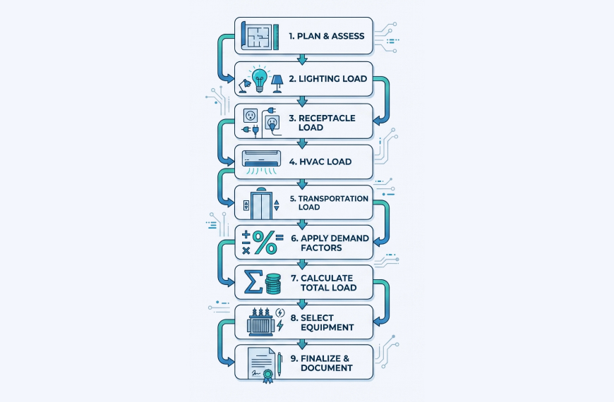
Here is the detailed methodology that engineers follow to perform a complete electrical load calculation for a building project.
Start by collecting the architectural floor plans, building specifications, and equipment schedules. You need to know the total built-up area, the number of floors, the types of spaces (offices, residential units, retail, parking, etc.), and any specialized areas like server rooms, kitchens, or laboratories.
If you are working on a project that is still in the early design phase, an AI floor plan generator can help you quickly produce structured layouts that include room areas and designations. Having accurate area data from the start is critical for load calculations.
Multiply the floor area of each space type by the applicable lighting power density (LPD) from the relevant code. For example, NEC Article 220.12 specifies general lighting load values per square foot based on occupancy type.
For a commercial office, the typical LPD might be around 1.0 W/sq.ft under ASHRAE 90.1. For a hospital, it could be 1.2 W/sq.ft. Multiply these values by the respective areas, then sum them up to get the total connected lighting load.
NEC Article 220.14 provides guidelines for calculating general-purpose receptacle loads. A common approach is to assign 180 VA per outlet or use a per-square-foot value. Apply demand factors from NEC Table 220.44 for non-dwelling occupancies when the total load exceeds certain thresholds.
List every piece of HVAC equipment with its rated power (in kW or HP). This includes compressors, condensers, AHUs, fans, and pumps. Convert horsepower to watts where necessary (1 HP = 746 W). Apply the motor efficiency factor to get the actual input power.
For buildings with large HVAC systems, the coordination between electrical and mechanical teams is crucial. AI-powered building design calculation tools can automate this coordination by pulling equipment data directly from HVAC sizing calculations into the electrical load schedule.
Add loads for elevators (consider the motor rating and the number of elevators), fire pumps (typically large motors with high starting currents), kitchen equipment, laundry equipment, and any other specialized systems.
For fire pump calculations, NEC Article 695 provides specific requirements. The fire pump motor is typically the largest single load in many buildings and has a significant impact on transformer and generator sizing.
Not all connected loads operate at full capacity simultaneously. Demand factors account for this reality. NEC Tables 220.42, 220.44, and other relevant tables provide demand factors for different load types and occupancy categories.
For example, the first 10 kVA of general lighting in a commercial building might be calculated at 100%, while everything over 10 kVA uses a demand factor of 50%. These factors reduce the calculated demand from the total connected load to a more realistic operating load.
Sum all the individual demand loads (lighting, receptacles, HVAC, special loads) after applying demand factors. This gives you the total demand load in kVA or kW. Use the formula:
Total Demand (kVA) = Total Demand (kW) / Power Factor
A typical power factor for commercial buildings ranges from 0.85 to 0.95. Apply the appropriate power factor to convert between kW and kVA.
Based on the total demand load, determine the required service entrance capacity, main breaker size, transformer rating, and feeder conductor sizes. Add a margin (typically 20-25%) for future expansion and safety.
Use the total demand in amperes to select the appropriate cable size, bus bar rating, and switchgear capacity. The formula for current is:
Current (A) = Total Demand (kVA) x 1000 / (Voltage x 1.732) [for three-phase systems]
Document the entire calculation in a structured load schedule that shows each panel, its connected loads, demand factors, and total demand. Create a single-line diagram (SLD) showing the power distribution from the utility supply through the main panel, sub-panels, and final circuits.
Modern platforms that offer automated drawing development can generate these schedules and diagrams automatically from your calculation inputs, saving hours of manual documentation work.
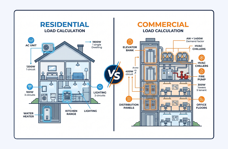
The approach differs between residential and commercial projects in several important ways.
Residential load calculations follow NEC Article 220 Part III (for dwelling units). The standard method uses the floor area to calculate general lighting and receptacle loads, then adds individual appliance loads (range, dryer, water heater, AC). Demand factors for residential are generally more aggressive because household loads rarely run simultaneously.
Commercial load calculations follow NEC Article 220 Part IV and are typically more complex. Commercial buildings have larger HVAC systems, elevator banks, fire pumps, and diverse occupancy types on different floors. The demand factors are less aggressive, and engineers must account for coincident peak demand across all systems.
For multi-story commercial buildings, the electrical load calculation becomes a major undertaking. Each floor may have different occupancy types (retail on ground floor, offices above, restaurant on the top floor), each with distinct load profiles. Tools that automate quantity takeoff and BOQ generation help streamline the documentation of equipment and materials needed for these complex projects.
Even experienced engineers make errors that can lead to undersized or oversized systems. Being aware of these common pitfalls helps you avoid them.
Ignoring future load growth is one of the most frequent mistakes. Buildings evolve over time. Tenants change, new equipment gets installed, and energy demands shift. Always include a growth factor (typically 15-25%) in your calculations.
Using incorrect demand factors happens when engineers apply residential demand factors to commercial buildings or vice versa. Always verify that the demand factors match the building type and the specific code edition being used.
Overlooking motor starting currents can lead to nuisance tripping of breakers and undersized feeders. Large motors like fire pumps and elevator motors draw 5-7 times their rated current during startup. The electrical system must handle these inrush currents.
Double-counting loads occurs when the same equipment appears in both the HVAC load schedule and the general power load schedule. Careful cross-referencing between disciplines prevents this error.
Not accounting for power factor leads to undersized transformers and conductors. Always convert between kW and kVA using the actual power factor of the loads.
Traditional electrical load calculations involve extensive manual work: collecting data from architectural drawings, cross-referencing with equipment schedules, applying code-specific demand factors, and producing documentation. This process can take days or even weeks for large projects.
AI-powered building design platforms are changing this workflow dramatically. Instead of manually entering each load into a spreadsheet and looking up demand factors in code tables, engineers can now input their building parameters and let automated calculation engines handle the math.
Platforms like DesignDrafter integrate electrical load calculations with the entire building design workflow. The AI engine can pull room areas directly from the floor plan, apply code-compliant lighting power densities, coordinate with HVAC equipment schedules, and generate the complete load schedule with supporting documentation.
This integrated approach offers several advantages. First, it reduces errors by eliminating manual data entry. Second, it saves time by automating repetitive calculations. Third, it ensures code compliance by applying the correct demand factors and standards automatically. And fourth, it enables rapid iterations when the building design changes during the project.
The AI Design Agent takes this even further by understanding the full building design context. It can perform electrical load calculations as part of a broader design workflow that includes HVAC sizing, plumbing calculations, and fire safety compliance, all coordinated on a single platform.
Before finalizing your electrical load calculation, run through this checklist to make sure nothing has been missed.
Verify that all floor areas match the latest architectural drawings. Confirm that lighting power densities are based on the correct code edition. Check that all HVAC equipment has been included with accurate ratings. Ensure that elevator and fire pump loads are calculated with proper starting current considerations. Apply demand factors from the correct code tables for the building type. Include a growth factor for future expansion. Verify the power factor assumption with actual equipment data. Cross-check the total demand against the utility supply capacity. Prepare the load schedule in a format acceptable to the local building authority. Generate the single-line diagram showing the complete power distribution path.
Completing this checklist systematically helps ensure that your electrical load calculation is thorough, code-compliant, and ready for submission.
Electrical load calculation is the backbone of safe, efficient, and code-compliant building electrical design. Whether you are an electrical engineer sizing a transformer for a high-rise tower, an architect coordinating MEP systems for a residential complex, or a contractor verifying the service entrance for a renovation project, getting the load calculation right is non-negotiable.
The process involves gathering building data, identifying and categorizing all loads, applying appropriate demand factors, and sizing the main distribution equipment. Following the step-by-step methodology outlined in this guide will help you produce accurate, defensible calculations for any building type.
As building designs grow more complex and project timelines get shorter, AI-powered tools are becoming essential for engineers who need speed without sacrificing accuracy. Platforms that integrate electrical calculations with BIM automation, floor plan generation, and multi-discipline coordination are helping design teams deliver better results in less time.
Ready to automate your electrical load calculations? Try DesignDrafter for free and experience how AI-powered building design software can transform your engineering workflow.
FAQ
Electrical load calculation is the process of estimating the total electrical power demand of a building by analyzing every connected load including lighting, HVAC equipment, receptacles, elevators, fire pumps, and special systems. Engineers perform this calculation to determine the correct sizes for conductors, circuit breakers, transformers, distribution panels, and the main service entrance equipment.
It is required by electrical codes such as the National Electrical Code (NEC) in the United States and IS/IEC 60364 standards in India before any electrical system design is finalized. Building authorities will not issue permits or occupancy certificates without code-compliant load calculations. Beyond compliance, the calculation protects building safety by preventing undersized systems that can overheat, cause frequent tripping, or create fire hazards.
Calculating the electrical load of a commercial building involves a structured sequence of steps. First, collect all architectural floor plans and equipment schedules to identify every space type and its area. Second, calculate the lighting load by multiplying each area by the applicable lighting power density from the relevant code, such as NEC Article 220.12 or ASHRAE 90.1. Third, add the receptacle and general power load using per-outlet values or per-square-foot figures from NEC Article 220.14.
Fourth, include all HVAC equipment loads, converting horsepower ratings to watts where necessary (1 HP equals 746 W). Fifth, add special loads such as elevators, fire pumps, kitchen equipment, and water pumps. Sixth, apply demand factors from the applicable NEC tables or local code to account for the fact that not all loads operate at full capacity simultaneously. Finally, sum the adjusted demand loads, apply the building’s power factor to convert between kW and kVA, and size the main service equipment with a 20 to 25 percent growth margin.
Connected load is the sum of the nameplate power ratings of all electrical equipment installed in a building, calculated as if every piece of equipment were operating at full capacity at the same time. Demand load is the portion of the connected load that is actually expected to be in use simultaneously during peak operating conditions.
The difference between the two is accounted for by demand factors, which are code-specified multipliers that reduce the theoretical maximum load to a realistic operating load. For example, NEC Table 220.42 allows the first 12,500 VA of general lighting in commercial buildings to be calculated at 100 percent, while loads above that threshold use a 50 percent demand factor. Using connected load without applying demand factors results in significantly oversized and unnecessarily expensive electrical systems, which is one of the most common mistakes in electrical load calculation for buildings.
In India, electrical load calculations for buildings are governed primarily by IS 732 and the IS/IEC 60364 series published by the Bureau of Indian Standards. These standards align closely with international IEC guidelines and cover the design, installation, and verification of electrical systems in all building types. State electricity boards and local development authorities may also impose additional requirements.
In the United States, the National Electrical Code (NEC/NFPA 70) is the primary standard. Articles 220, 230, and 695 are the most directly relevant for building load calculations, covering branch circuit loads, feeder sizing, service entrance calculations, and fire pump requirements. In the United Kingdom and many Commonwealth countries, BS 7671 (IET Wiring Regulations) governs electrical installation design including load assessment methodology. Engineers must always verify which code edition and local amendments apply to their specific project location.
Demand factors are code-specified percentages applied to connected loads to reflect the realistic probability that not all equipment in a building will operate at full rated power simultaneously. They reduce the total connected load to a more accurate demand load, which is then used to size conductors, panels, transformers, and service entrance equipment.
Demand factors are found in the applicable electrical code for the project. In the NEC, the primary tables are 220.42 for general lighting, 220.44 for non-dwelling receptacles, and 220.56 for commercial cooking equipment. Different building types have different demand factor schedules. Residential buildings typically use more aggressive demand factors than commercial buildings because household loads are less coincident. Applying the wrong demand factor table, such as using a residential table for a commercial project, is a common and consequential error that leads to undersized electrical systems.
The formula for calculating total electrical demand in a three-phase system involves two conversions. First, convert the total demand from kilowatts to kilovolt-amperes using the power factor of the building’s loads: Total Demand in kVA equals Total Demand in kW divided by the Power Factor. For most commercial buildings, the power factor ranges from 0.85 to 0.95.
Second, convert the total kVA demand to amperes using the three-phase current formula: Current in Amperes equals (Total Demand in kVA multiplied by 1000) divided by (System Voltage multiplied by 1.732). The 1.732 factor is the square root of 3, which accounts for the phase relationship in three-phase systems. For a building with a total demand of 500 kVA connected to a 415V three-phase supply, the main current would be approximately 695 amperes. This figure is then used to select the main circuit breaker rating, bus bar size, and incoming cable cross-section.
AI-powered building design platforms improve electrical load calculations in three significant ways. First, they eliminate manual data entry errors by reading room areas and occupancy types directly from floor plans and applying the correct lighting power densities and demand factors automatically based on the building type and applicable code. This removes one of the most common sources of calculation error in complex multi-floor projects.
Second, they enable real-time coordination between disciplines. When an HVAC engineer updates equipment ratings, an AI-integrated platform can instantly reflect those changes in the electrical load schedule without requiring a separate manual update cycle. Third, they dramatically reduce the time required to produce load schedules and single-line diagrams for large commercial or mixed-use buildings, where manual calculation can take days. For engineers working on projects with tight design timelines, this speed advantage directly affects project delivery without compromising code compliance or calculation accuracy.

March 27 , 2026

May 25 , 2026

May 9 , 2026