In Short
The best CAD to BIM software in 2026 balances accuracy and speed by matching output detail, or LOD, to the actual project stage rather than defaulting to maximum detail. Automated CAD to BIM tools commonly finish conversions in hours that manual modeling takes days or weeks to complete, though manual work still wins on complex or poor quality drawings. LOD runs from LOD 100 concept massing through LOD 500 as built models, and mismatching this to the project stage is the most common cause of rework. DesignDrafter focuses on producing coordination ready models aligned with Indian code references, avoiding the second manual pass many global tools require.
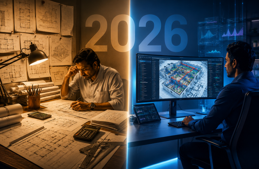
The best CAD to BIM software in 2026 does more than convert lines into 3D shapes. It preserves the right level of detail for the project stage, keeps data consistent across disciplines, and does this in hours instead of weeks. That combination of accuracy and speed is what separates a genuinely useful tool from one that just adds a modeling step nobody asked for.
Firms still handle this conversion in very different ways. Some outsource it to a modeling team that manually rebuilds every wall and duct from a 2D drawing set. Others have started using automated CAD to BIM tools that read the drawing and generate a model directly. Both approaches can work, but they are not close to equal in cost or turnaround time, and picking the wrong one for your project stage is an easy way to pay for detail you did not need or miss detail you did.
This comparison looks at what actually separates the faster tools from manual modeling, why the level of detail question matters more than most buyers realize, and how a few named tools in this space stack up on real turnaround and output quality.
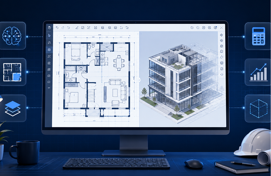
CAD to BIM conversion is the process of turning flat 2D drawings into a coordinated 3D building model with data attached to each element. Accuracy matters because a model with the wrong level of detail either slows down every team that touches it afterward or gets rejected outright by a client expecting more.
This is not just a geometry exercise. A converted BIM model needs to carry the right information for its intended use, structural sizes for engineers, duct routing for MEP consultants, material data for cost estimators. Get the conversion wrong at this stage and every downstream team inherits the error, often without realizing where it came from until a clash review or site visit catches it.
Picture a typical scenario. A structural engineer receives a converted model expecting accurate column and beam sizes, only to find the tool guessed at dimensions from a poorly labeled drawing layer. The engineer now has to manually verify every structural element before doing any real work, which erases most of the time the conversion was supposed to save. This is the quiet cost of an inaccurate conversion. It rarely shows up as an obvious failure. It shows up as extra hours nobody budgeted for.
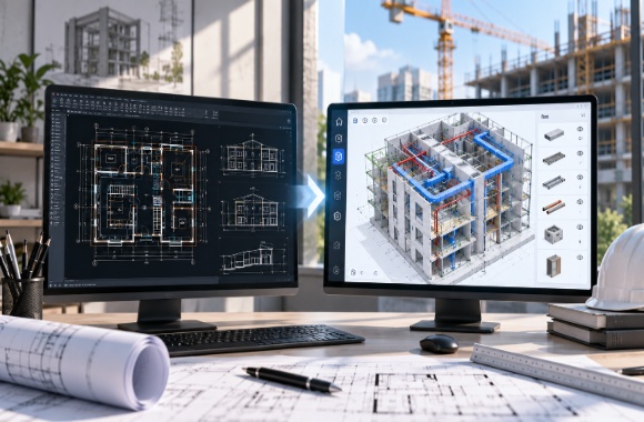
Automated CAD to BIM reads existing drawing data directly and builds a model from it, instead of a modeler manually rebuilding every element by hand. Firms adopt it because manual conversion on a full drawing set can take days to weeks, while automated tools commonly finish the same task in hours.
Manual modeling still has its place, especially on drawings with poor line quality or unusual geometry that automated tools misread. But for a standard drawing set, most of the modeling work is repetitive. Walls follow consistent line weights, doors and windows follow a symbol library, and structural grids repeat across floors. That repetition is exactly what automated CAD drawing to BIM tools are built to handle, freeing up the modeling team for the parts that actually need judgment.
Think about a typical mid sized residential project with twelve floor plans that repeat with minor variations. A manual modeler working through each plan individually might spend a full week rebuilding walls, doors, and fixtures that are nearly identical floor to floor. An automated tool reading the same drawing set can apply the same logic across every repeated plan in a fraction of that time, leaving the modeler to focus only on the floors that genuinely differ. The time saved scales with how repetitive the building actually is, which is worth checking before assuming automation will help equally on every project type.
LOD, or Level of Development, defines how much detail and reliability a BIM element carries at a given project stage, and it directly determines whether your conversion tool is doing too little or too much for the job. Converting a concept drawing to a fabrication ready model wastes time, and the reverse leaves your team without the detail they need.
The LOD framework runs from LOD 100 through LOD 500. LOD 100 covers basic massing with no real dimensions, useful for early feasibility work. LOD 200 adds approximate sizes and basic systems. LOD 300 is where most coordination happens, with exact dimensions and placement good enough for clash detection. LOD 350 adds installation details like connections and fittings. LOD 400 goes further into fabrication level detail for manufacturing. LOD 500 is the as built model used for facility management after handover. A tool that only outputs LOD 200 quality is fine for early design but will not survive a coordination meeting. A tool that forces LOD 400 detail onto a concept stage drawing is just slowing everyone down for no reason.
A poorly matched conversion does not usually fail loudly. It shows up later, as rework that could have been avoided if the tool and the project stage had been matched correctly from the start.
On the low detail side, a team using an LOD 200 output for what should have been LOD 300 coordination work often finds clashes during construction that a proper coordination model would have caught earlier, when fixing them was still cheap. On the high detail side, a team that pays for LOD 400 fabrication detail on a concept design that is still likely to change ends up redoing that detailed work anyway once the design shifts, since fabrication level models are expensive to update. Both mistakes come from the same root cause, treating LOD as a fixed setting rather than a decision tied to what the project actually needs at that specific stage. Getting this match right the first time is usually cheaper than fixing either kind of mismatch later.
Here is how a few known approaches in this space compare on turnaround and typical output quality, based on their published claims and documented workflows:
| Tool or Approach | Typical Turnaround | Output Detail | Best Fit |
| DesignDrafter | Hours | LOD 300 to 350, India code aligned | Architects and MEP consultants needing coordination ready models |
| Swapp.ai | Days instead of weeks | Full construction documentation | Multifamily and hospitality projects at scale |
| Snaptrude | Minutes for early models | LOD 300 concept models | Early stage program to BIM conversion |
| Manual outsourced modeling | Days to weeks | Varies by modeler | Complex or non standard drawings needing human judgment |
The pattern across the faster tools here is consistent. Swapp.ai reports producing full construction documents in days rather than weeks for repeatable building types, and industry coverage of BIM automation tools notes that even simpler scripting tools like Dynamo and pyRevit deliver 30 to 40 percent time savings on low value documentation tasks alone. Manual outsourced modeling still wins on judgment calls, oddly shaped buildings, poor quality source drawings, or projects where a human needs to make a call the software cannot. For everything else, the case for automation keeps getting stronger every year this gap in speed holds.
It is worth noting that speed claims like these are usually measured on the vendor's own best case projects, repeatable building types with clean source drawings. Your actual results will depend heavily on how close your project matches that best case, which is exactly why testing a tool on your own drawing set matters more than trusting a published benchmark on its own.
A quick checklist beats a sales demo every time, since a demo is almost always run on a drawing set chosen to make the tool look good. Before choosing a tool for a real project, work through this short checklist:
These mistakes show up often enough in reviewed projects that they are worth checking for directly before a conversion goes wrong.
DesignDrafter's approach to automated CAD to BIM keeps the conversion tied to the project stage it is meant for, producing coordination ready models without pushing every drawing to unnecessary fabrication level detail. The platform's design calculation tools carry structural data through the conversion, so engineers are not starting from a blank model after the geometry comes across.
For firms working on Indian projects specifically, the bigger gap in this space has less to do with the conversion itself and more to do with what happens after. Most CAD to BIM tools were not built with Indian code references or local drawing conventions in mind, which means a converted model still needs manual rework to match IS code expectations. DesignDrafter's quantity extraction tools and architects solution are built around closing that specific gap, keeping the converted model usable for Indian projects rather than needing a second pass to make it locally relevant.
Most global CAD to BIM tools were built around US or European drawing conventions, symbol libraries, and code references, and they carry those assumptions into every conversion regardless of where the project actually sits. An Indian firm using one of these tools often finds the converted model technically correct but still needing a full pass to align units, structural code references, and drawing conventions with local practice. That second pass is easy to underestimate until it is already eating into the time the automation was supposed to save.
Picking the right CAD to BIM software comes down to matching the tool to your actual project stage and building type, not just picking whatever converts fastest. BIM conversion tools that force too much or too little detail waste time either way, and the fastest tool on paper is not always the right fit for your specific drawing set or building type.
If you are comparing options for an upcoming project, test the checklist above against your own drawings before committing, rather than relying on a vendor demo that was likely chosen because it converts cleanly. Check current pricing if DesignDrafter looks like a fit for your workflow, and weigh it against how much manual rework your current process actually needs today.
Founder
Manas Krishna is a Mechanical Engineer and infrastructure technology entrepreneur with 20+ years of experience in MEP (Mechanical, Electrical, and Plumbing) engineering, public health engineering, and transport infrastructure projects across India.
FAQ

CAD to BIM conversion software turns flat 2D drawings into coordinated 3D building models with data attached to each element. It is used to speed up modeling for design coordination, clash detection, quantity takeoff, and facility management after a project is built.
Automated CAD to BIM is generally accurate on standard drawings with consistent line weights and symbol libraries, but can misread unusual geometry or poor quality source files. Manual modeling still performs better on complex or non standard drawings where human judgment is needed.
CAD drawing to BIM converts existing 2D drawings into a 3D model, while scan to BIM builds a model from a point cloud captured by laser scanning an existing building. They solve different problems, and a project only needs scan to BIM when no reliable drawing exist.
Match the LOD to your project stage. Early design work only needs LOD 100 to 200, coordination and clash detection need LOD 300, and fabrication or manufacturing needs LOD 400. Choosing a higher LOD than the stage requires wastes time without adding useful value.
This usually happens when the conversion tool only processes geometry and ignores the attributes attached to CAD layers or blocks. Confirm before conversion that the tool maps layer and block data into the BIM element properties your structural, MEP, or cost teams actually use.
Automated tools are generally faster and more cost effective for standard drawing types like typical floor plans and structural grids. Outsourced manual modeling is still worth it for complex geometry, poor quality source drawings, or projects where a modeler needs to make judgment calls the software cannot.
BIM conversion tools are built specifically to read existing CAD drawings and generate a model automatically, while general BIM authoring software like Revit is used to build models manually from scratch. Some platforms combine both, letting you convert first and then refine manually inside the same tool.
Yes. DesignDrafter is built around producing coordination ready BIM models aligned with Indian code references, aimed at architects and MEP consultants who need converted models that do not require a second manual pass to become locally usable on Indian project sites.
Manual conversion on a full drawing set commonly takes days to weeks depending on complexity, while automated tools often complete the same conversion in hours. The exact time depends on drawing quality, building type, and how much detail the target LOD requires.
Test the tool on one of your own drawing sets rather than a vendor demo file, confirm the output LOD matches your project stage, and check that converted data fields match what your downstream teams actually need before relying on the model for coordination work.