In Short
This guide is written for architects, MEP engineers, contractors, and anyone who needs to read, draw, or verify architectural floor plans in India in 2026. It covers every major category of floor plan symbol including structural walls, door and window types, staircase notation, and a full MEP symbol library for HVAC, electrical, plumbing, and fire fighting systems that most competing guides completely skip. The guide includes India-specific architectural abbreviations and notations used daily in Indian construction drawings: FFL, NGL, SFL, RCC, AAC, OHT, UGT, STP, BHK, and more, with their full forms and practical usage context. It also covers drawing sheet reference symbols (section marks, detail bubbles, elevation tags, revision clouds) and explains what happens when floor plan symbols are used incorrectly and the downstream project consequences. Practical links throughout connect symbol knowledge to DesignDrafter's AI floor plan generation, MEP calculation, BOQ extraction, and BIM automation tools, showing how symbol-level accuracy translates into connected, code-compliant design outputs.
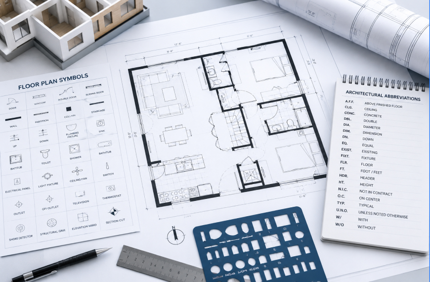
Floor plan symbols are standardized icons, lines, and shapes used on architectural drawings to represent structural elements, doors, windows, MEP systems, and fixtures in a compact, universally readable format. Architectural abbreviations are the shorthand labels that work alongside those symbols to communicate materials, room types, drawing references, and specification notes within the confined space of a 2D plan. Together, they're the visual language that every architect, MEP engineer, contractor, and site supervisor must read fluently to deliver a building without costly misinterpretations.
If you've ever stared at a drawing set and wondered what a dashed line means, why a door arc points one way, or what "FFL" refers to in an Indian construction drawing, this guide answers all of it. And if you're working with DesignDrafter's AI floor plan generation to produce build-ready layouts, understanding what those generated symbols represent helps you review, refine, and present outputs with confidence.
Most online guides covering floor plan symbols are written for homeowners or Western real estate audiences. They cover the basics: doors, windows, stairs, a few furniture icons. What they miss is what professionals actually need: MEP symbols on engineering drawings, Indian-specific notation like FFL and NBC staircase dimensions, drawing sheet reference symbols, and an explanation of what happens when symbols are used incorrectly or inconsistently across a drawing set. This guide fills that gap.
Floor plan symbols are important because they compress enormous amounts of information into a small drawing space without losing precision. A single door symbol tells you the door's swing direction, approximate width, and opening clearance requirement in one compact arc. A wall hatch pattern tells you whether that wall is brick, concrete, insulation, or glass. Without these symbols, every floor plan would need paragraphs of text to describe what a skilled reader can absorb in seconds.
Floor plan symbols matter for professionals because misreading them causes real problems: a contractor who reads a pocket door symbol as a hinged door leaves the wrong rough opening. A structural engineer who misses a column grid reference symbol misaligns loads. An MEP engineer who confuses a supply air symbol with a return air symbol reverses duct routes that then require redesign and re-coordination.
According to the American Institute of Architects, "a well-crafted symbol isn't just notation, it's a decision made visible." That's exactly right. Every symbol on a floor plan represents a design or engineering decision that someone made, documented, and is now asking a contractor to execute precisely.
Walls are the most fundamental element on any floor plan. Different wall types use different line weights and hatch patterns to convey their structural role, material, and location in the building:
In frame structures (which dominate Indian commercial and multi-story residential construction), columns are shown as solid filled squares or rectangles at their actual plan dimensions. Structural grid lines run through column centerlines and are labeled alphabetically (A, B, C) in one direction and numerically (1, 2, 3) in the other.
Grid references are critical because they're the coordinate system that every discipline uses to communicate location. When an MEP engineer says "the AHU is at grid B3," every consultant on the project immediately knows where it is without needing to measure from a wall. If columns are not shown correctly in a floor plan or grid lines are missing, MEP coordination becomes significantly harder.
DesignDrafter's Smart BIM Automation reads structural geometry from CAD or BIM models and translates walls, columns, and grid lines into structured Revit objects, preserving the spatial intelligence that downstream MEP coordination depends on.
Door symbols are among the most commonly misread elements on floor plans, particularly by clients and non-technical stakeholders reviewing drawings for the first time.
In India, door symbols must also convey compliance with NBC minimum dimensions: 900mm clear opening width for main entrance doors, 800mm for internal room doors, and 1000mm for accessible doorways in buildings covered by universal design requirements.
Window symbols use a standard set of three parallel lines within the wall thickness to indicate a window opening. Variations communicate the window type:
Window symbols on Indian residential drawings should note the sill height (typically 900mm from FFL for privacy, lower for view windows) and the lintel level, because the space between lintel and slab soffit is where MEP services often route above false ceiling lines.
Staircases are shown as a series of parallel horizontal lines representing individual treads, with an arrow indicating the direction of ascent labeled "UP" or "DN". The number of risers is typically noted alongside (e.g., "17R" means 17 risers in that flight).
In India, staircase designs must comply with NBC requirements: minimum step height (riser) of 150mm and maximum of 190mm, minimum tread depth of 250mm, and minimum stair width of 1.0 metre for residential and 1.5 metres for commercial buildings (AECORD, 2026). These dimensions are often annotated directly on the stair symbol in permit submission drawings.
On multi-story plans, the cut line through a staircase is typically shown with a diagonal break line across the treads, indicating that the stair continues above the cut plane. The lower portion of the stair (below the cut) is shown with solid lines; the upper portion (above cut) uses dashed lines.
Ramps are shown as rectangles with a diagonal arrow indicating slope direction and gradient (e.g., "1:12" for accessible ramps per NBC disability provisions). Gradient notation is especially important in Indian commercial buildings where RERA and municipal authority approvals now increasingly check for accessible design compliance.
This is where most floor plan symbol guides stop short. MEP symbols are where the real complexity lives for engineers, and misreading them has the most expensive consequences on construction sites. DesignDrafter's building design calculation platform auto-generates layouts from MEP calculations, and the symbols it places carry specific technical meaning that every team member handling the drawings must understand.
HVAC systems have the most extensive symbol vocabulary on any MEP drawing set:
Electrical floor plans use a dense set of symbols that contractors must read accurately for first-fix wiring:
For architects working with DesignDrafter's solutions, understanding that electrical symbols in AI-generated layouts directly reflect the load calculation outputs helps in verifying that the placement and specification of outlets, panels, and light points are calculation-driven, not decorative.
Plumbing symbols appear on dedicated plumbing drawings but are often also shown schematically on architectural floor plans to indicate wet area fixture locations:
DesignDrafter's MEP consultant solution generates plumbing layouts directly from water demand calculations per IS:1172 and NBC standards, so the symbols placed on the drawing reflect actual pipe sizes and fixture unit loads rather than estimated positions.
Fire fighting symbols are a distinct category that many general floor plan guides completely skip:
This is one of the biggest gaps in competing guides. Professionals use drawing sheet reference symbols daily, but almost no consumer-facing floor plan guide covers them. These symbols navigate you through a multi-sheet drawing set.
For teams using DesignDrafter's AI Design Agent, these reference symbols are automatically populated in generated drawing sets when the platform's BIM automation engine produces annotated sheets from model data, eliminating the manual placement of hundreds of cross-reference tags across large drawing sets.
Most floor plan guides are written for Western audiences and miss the notation conventions Indian architects, engineers, and contractors use daily. Here are the ones that matter most in Indian construction drawings:
| Abbreviation | Full Form | What It Means in Indian Practice |
| FFL | Finished Floor Level | Height of completed floor surface above a datum. In India, ground floor FFL is typically 0.6-1.0m above natural ground level (AECORD, 2026). |
| SFL | Structural Floor Level | Height of the structural slab before any screed or finish is applied. |
| NGL | Natural Ground Level | Existing ground level before any site leveling or earthwork. |
| GL | Ground Level | Refers to finished site level or, in smaller drawings, can also mean glazing. Context determines meaning. |
| RL | Reduced Level | A surveying level referenced to a benchmark datum, used in site plans and sections. |
| TOW | Top of Wall | The height at which a wall terminates, typically used in parapet and boundary wall drawings. |
| BOF | Bottom of Footing | Foundation depth reference used in structural drawings. |
| Abbreviation | Full Form |
| RCC | Reinforced Cement Concrete |
| PCC | Plain Cement Concrete |
| AAC | Autoclaved Aerated Concrete (block type) |
| MS | Mild Steel |
| SS | Stainless Steel |
| GI | Galvanized Iron |
| UPVC | Unplasticized Polyvinyl Chloride (pipe and window frame material) |
| Al / Alum | Aluminium (window and door frame profiles) |
| PT | Precast or Post-Tensioned (context determines) |
| WC | Water Closet (toilet) |
| OHT | Overhead Water Tank |
| UGT | Underground Water Tank |
| STP | Sewage Treatment Plant |
| MH | Manhole |
| CP | Chrome Plated (fittings finish) |
| TW | Top Width (road or embankment cross-section) |
| Abbreviation | Full Form |
| BHK | Bedroom, Hall, Kitchen (Indian residential unit type) |
| LT | Living and/or Lounge area |
| MBR | Master Bedroom |
| BR | Bedroom |
| KIT | Kitchen |
| UTL | Utility area |
| STR | Storeroom |
| BAL | Balcony |
| CRDN | Corridor |
| STLT | Staircase Landing |
| LIFT | Elevator / Lift shaft |
| C/C | Centre to Centre (dimension reference) |
| CL | Centreline |
Beyond India-specific notation, these abbreviations appear across drawing sets globally and are used in most CAD and BIM platforms:
This section doesn't exist in any competing guide. But it's arguably the most practically useful one.
Incorrect or inconsistent floor plan symbols don't just look unprofessional. They cause measurable project problems:
Wrong door swing direction means a door that was designed to open against a wall instead swings into the room center, creating a circulation hazard and often requiring relocation after rough carpentry is complete. Rework cost: moderate, but disruptive.
Missing grid references on columns forces MEP engineers to measure from walls when locating equipment, introducing dimensional errors that compound through every subsequent discipline. On a 50,000 sq ft commercial floor, this can misplace equipment by enough to create ceiling bulge conflicts.
Confusing supply air and return air symbols (a common error when non-mechanical staff redraw HVAC layouts) produces a drawing where the duct routes are reversed. Contractors who build from that drawing create a system that circulates air backwards, which is a commissioning failure that requires duct rerouting.
Omitting FFL notation on Indian residential drawings often results in the contractor defaulting to a lower ground floor level than the designer intended, creating drainage issues, flooding vulnerability, and requiring retrospective site filling.
Using NTS (not to scale) without a graphic scale bar means contractors cannot use the drawing for setting out, because there's no reliable reference dimension to work from. Every dimension must then be extracted from annotated notes, which are often incomplete.
DesignDrafter's quantity extraction module reads symbol data from drawings to generate BOQs. When symbols are correctly placed and annotated, the quantity extraction is accurate and procurement-ready. When symbols are wrong, the extracted quantities are wrong too, which cascades into procurement errors and cost variances.
For design firms managing drawing quality across multiple disciplines, DesignDrafter's solutions for design firms provide a connected workflow where MEP calculations drive symbol placement automatically, reducing the manual annotation errors that cause downstream project problems.
Modern AI floor plan generation tools don't just produce pretty pictures. They generate spatially accurate floor plans where every symbol has a meaning, a position, and a connection to the design data driving it.
When DesignDrafter's AI Floor Plan Studio generates a floor plan from a brief, it places door symbols with correct swing directions based on room adjacency and circulation logic, window symbols at proportionally sized openings with appropriate sill and lintel positions, and room labels with standard abbreviations aligned to Indian residential conventions.
The practical implication for architects using DesignDrafter's floor plan generation service is that the generated layout is not just a visual sketch to redraw. It's a spatially structured plan where the symbols carry coordinate data, element classifications, and dimensional information that flows directly into MEP calculations, BOQ extraction, and BIM coordination.
When an architect reviews a generated floor plan, reading the symbols correctly means reading the design intent. A pocket door symbol where a hinged door would create a circulation conflict is a deliberate placement. A column grid that locks structural spans to efficient module sizes is an engineering decision expressed through grid notation. Understanding what the symbols mean is what allows an architect to verify that the generated design is right for their project, not just geometrically plausible.
Floor plan symbols and architectural abbreviations are the shared vocabulary of the built environment. Every architect, MEP engineer, contractor, site supervisor, and client who needs to understand a building before it's built must be able to read this language fluently. Misreading a symbol or misusing an abbreviation creates downstream errors that range from annoying rework to expensive construction mistakes.
The core takeaway from this guide is that floor plan symbols are not just notation conventions. They're precision communication tools where the specific shape, line weight, orientation, and accompanying abbreviation each carry distinct technical meaning. A door arc is not just "a door." It's a specific door type, opening in a specific direction, requiring a specific rough opening and clearance. Getting it right is what allows a two-dimensional drawing to become a three-dimensional building without ambiguity.
For Indian architects and MEP engineers, the additional layer of India-specific notation including FFL, NBC-compliant stair dimensions, OHT, UGT, STP, and RCC versus AAC block wall distinctions is the practical vocabulary that makes Indian construction drawings readable across consulting, contracting, and authority approval workflows.
For teams working with AI-assisted design platforms, understanding symbols is what allows you to interpret, verify, and confidently issue AI-generated floor plans and MEP layouts for construction. The platform produces the symbols. Your knowledge of what they mean is what allows you to ensure they're correct.
Start generating build-ready floor plans with correctly placed symbols at designdrafter.com/generate-floor-plan. For MEP engineers who need calculation-driven symbol placement on HVAC, plumbing, electrical, and fire fighting drawings, explore the full calculation workflow at designdrafter.com/design-calculation.
References & sources
Citations that back the claims in this post.
AECORD How to Read Architectural Drawings
aecord.com
Architecture Lab Architectural Symbols Guide
architecturelab.net
National Building Code of India (BIS)
bis.gov.in
Founder
Manas Krishna is a Mechanical Engineer and infrastructure technology entrepreneur with 20+ years of experience in MEP (Mechanical, Electrical, and Plumbing) engineering, public health engineering, and transport infrastructure projects across India.
FAQ

Floor plan symbols are standardized icons, shapes, and line types used on architectural drawings to represent structural elements, doors, windows, MEP systems, furniture, and fixtures in a compact, universally readable format. They are important because they compress complex design information into a small 2D drawing space without losing precision. Common floor plan symbols include door arcs, window triple lines, wall hatch patterns, stair treads with directional arrows, electrical outlet circles, and plumbing fixture outlines.
The most common architectural abbreviations include: FFL (Finished Floor Level), RCC (Reinforced Cement Concrete), TYP (Typical), RO (Rough Opening), EQ (Equal), NTS (Not to Scale), AFF (Above Finished Floor), CLG (Ceiling), WC (Water Closet), OHT (Overhead Tank), UGT (Underground Tank), CL (Centreline), and C/C (Centre to Centre). In Indian construction drawings, abbreviations like BHK, FFL, NGL, STP, and MH are used daily across residential, commercial, and infrastructure projects.
Different line types on a floor plan convey different information. Thick solid lines represent exterior walls or structural elements. Thin solid lines show interior partitions and furniture. Dashed lines indicate elements above the cut plane, such as overhead beams, upper floor overhangs, or hidden features like pocket door recesses. Dotted lines mark appliances, cabinets, or elements that are part of the design but not structural. Dash-dot lines typically indicate gridlines or centrelines in structural and MEP drawings.
Floor plan symbols cover structural and architectural elements: walls, doors, windows, stairs, columns, and furniture. MEP symbols are a specialist category used on mechanical, electrical, and plumbing drawings to represent HVAC equipment (AHUs, diffusers, ducts), electrical components (outlets, switches, distribution boards), plumbing fixtures (WCs, lavs, pipes), and fire fighting equipment (sprinkler heads, hydrants, hose reels). MEP symbols require specialist knowledge to read correctly because confusing supply air with return air, or hot water with cold water piping, creates expensive construction errors.
FFL stands for Finished Floor Level and refers to the height of the completed floor surface above a reference datum, typically the survey benchmark or the natural ground level. In Indian residential buildings, ground floor FFL is commonly set 0.6 to 1.0 metres above Natural Ground Level (NGL) to account for drainage, dampness prevention, and NBC requirements. FFL is a critical notation because it determines the height relationship between floors, the structural slab thickness, and the connection to external site levels.
A door symbol on a floor plan consists of a thin rectangular outline representing the door panel and a quarter-circle arc showing the door’s swing path when fully open. The arc’s radius equals the door width. The direction the arc sweeps tells you which side the hinges are on and whether the door opens into or out of the room. A 90-degree arc is a standard single-leaf hinged door. Double arcs indicate a double-leaf door. Overlapping rectangles indicate a sliding door. A panel disappearing into a wall indicates a pocket door.
A section mark is an arrow with a letter and sheet number (e.g., “A/A-2”) placed on a floor plan to indicate that a cross-section view labeled “A” can be found on drawing sheet A-2. The arrow direction shows the viewing direction of the section cut. A detail bubble is a circle divided by a horizontal line with a detail number above and a sheet number below (e.g., “3/A-5”), indicating that enlarged detail number 3 is on sheet A-5. These cross-reference symbols are essential for navigating large drawing sets efficiently.
Standard HVAC symbols include: supply air diffuser (rectangle or square labeled “SA”), return air grille (labeled “RA” or “REG”), exhaust grille (labeled “EAG”), AHU (rectangle labeled “AHU” with duct connections), FCU (smaller rectangle labeled “FCU”), ductwork (single or double lines with size annotations like “600×400”), VRV/VRF indoor unit (labeled “IDU”), and refrigerant pipe connections (thin lines labeled “RL” for liquid and “RG” for gas). Confusing supply and return air symbols is one of the most common and costly drawing errors in MEP coordination.
Staircase symbols on Indian floor plans show individual treads as parallel horizontal lines with a directional arrow labeled “UP” or “DN” and the number of risers noted (e.g., “17R”). A diagonal break line across the treads shows the floor plan cut level, with the lower portion in solid lines and the upper continuation in dashed lines. NBC requirements specify minimum riser height of 150mm, maximum 190mm, minimum tread depth of 250mm, and minimum stair widths of 1.0m for residential and 1.5m for commercial buildings.
AI floor plan generation software like DesignDrafter places floor plan symbols with spatial intelligence derived from the design calculations and space planning logic driving the layout. Door symbols are placed with correct swing directions based on circulation analysis. Window symbols reflect proportionally sized openings at appropriate sill heights. Room labels use standard abbreviations aligned to Indian residential conventions. MEP calculation platforms place HVAC, plumbing, and electrical symbols at positions and sizes derived from load calculations, producing drawings where symbol placement is calculation-driven rather than manually estimated.